
Ignition system and method for operating an ignition system

a technology of ignition system and ignition system, which is applied in the direction of ignition automatic control, machines/engines, mechanical equipment, etc., can solve the problems of spark breakage, small installation space of modern engine concepts, and stronger erosion of spark plug electrodes, so as to reduce the energy requirement of the ignition system, simple and rapid achievement, and cost-effective and space-saving

Inactive Publication Date: 2016-09-29
ROBERT BOSCH GMBH
View PDF5 Cites 12 Cited by
  • Summary
  • Abstract
  • Description
  • Claims
  • Application Information

AI Technical Summary

Benefits of technology

The present invention provides a method for ascertaining the energy requirement of an ignition system without the need for additional hardware. This is achieved by measuring the electrical parameter of the ignition spark, such as the ignition spark current or voltage, and comparing it with a reference threshold value to determine when the energy should be lowered or increased to avoid erosion or unwanted spark breakaway. The method can be implemented using existing electronic control units and pneumatic components within the ignition system, with minimal additional cost or space. The invention also allows for the classification of the electrical parameter and the assignment of suitable switch-on times for the boost converter based on engine operating states to optimize the ignition process.

Problems solved by technology

This conflicts with the requirements for smaller installation spaces of modern engine concepts (“downsizing”).
High spark currents are more robust in the combustion chamber as opposed to turbulent current, but they are known to result in stronger erosion of the spark plug electrodes.
In contrast, small spark currents may result in a spark breakaway in the case of turbulent current in the combustion chamber, in the event the ignition spark energy or the spark current falls below a defined limit.
The prior known systems do not satisfactorily exhaust the potential for spark stabilization in ignition systems.
A particularly severe electrode wear occurs in commercially available spark plugs, for example, at spark currents greater than 100 mA.

Method used


Image

  • Ignition system and method for operating an ignition system
  • Ignition system and method for operating an ignition system
  • Ignition system and method for operating an ignition system

Examples


Embodiment Construction

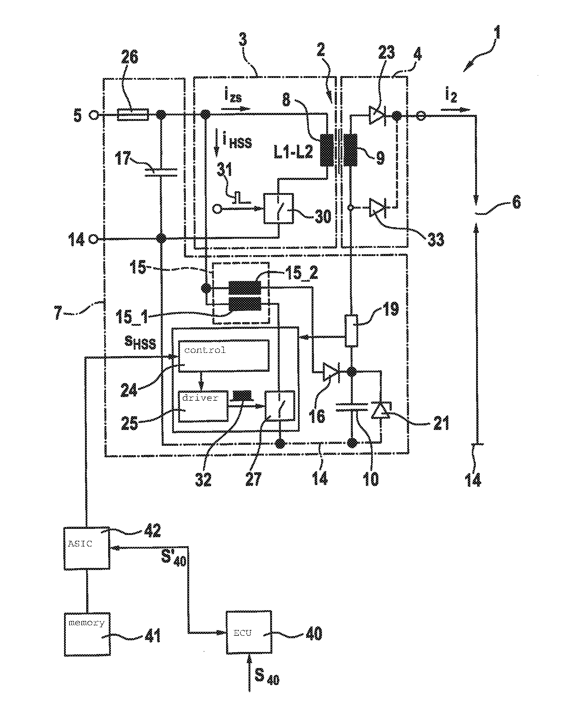
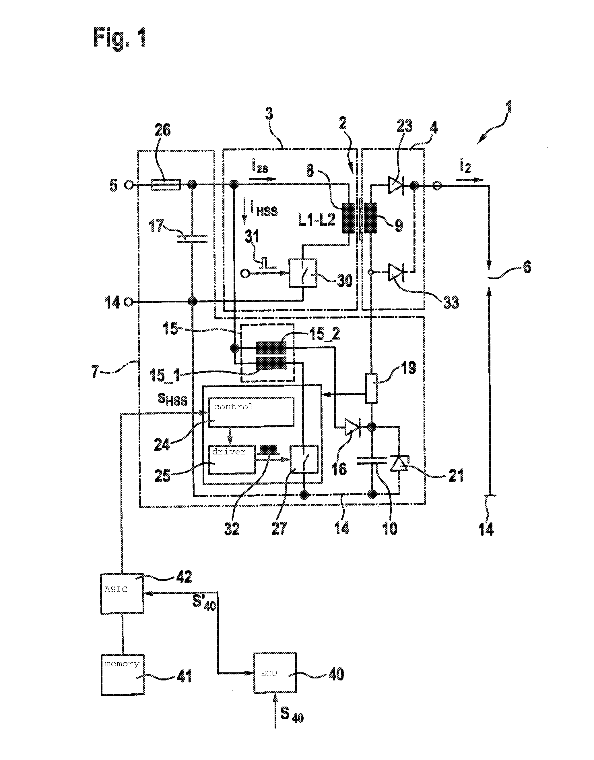
[0021]FIG. 1 shows a circuit of an ignition system 1, which includes a step-up transformer 2 as a high voltage generator, the primary side 3 of which may be supplied with electrical energy from an electrical energy source 5 via a first switch 30. Step-up transformer 2 made up of a primary coil 8 and a secondary coil 9 may also be referred to as a first voltage generator or primary voltage generator. A fuse 26 is provided at the input of the circuit, in other words, therefore, at the connection to electrical energy source 5. In addition, a capacitance 17 for stabilizing the input voltage is provided in parallel to the input of the circuit or in parallel to electrical energy source 5. Secondary side 4 of step-up transformer 2 is supplied with electrical energy via an inductive coupling of primary coil 8 and secondary coil 9, and includes a diode 23 known from the related art for suppressing the powering spark, this diode being alternatively substitutable with diode 21. A spark gap 6, ...


PUM


Abstract

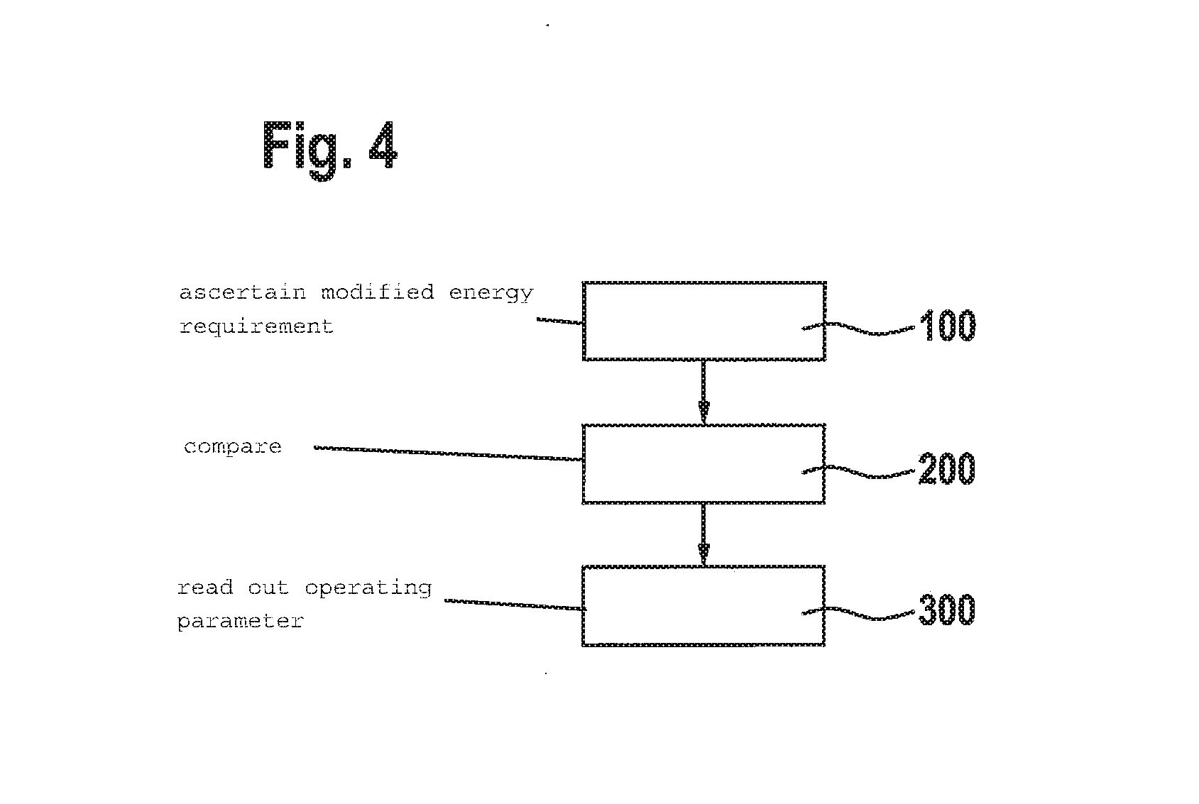
A method is described for operating an ignition system for an internal combustion engine, including a primary voltage generator and a boost converter for maintaining a spark generated with the aid of the primary voltage generator. An ascertainment of a modified energy requirement for an ignition spark to be maintained with the aid of the boost converter is followed by a modification of a switch-on time of the boost converter relative to a switch-off time of the primary voltage generator.

Description

FIELD[0001]The present invention relates to a method for operating an ignition system for an internal combustion engine, including a first voltage generator (also “primary voltage generator”) and a boost converter. The present invention relates, in particular, to an avoidance of an undesirable spark breakaway during operation.BACKGROUND INFORMATION[0002]Ignition systems are used in order to ignite an ignitable mixture in a combustion chamber of a spark ignited internal combustion engine. For this purpose, an ignition spark gap is acted on with electrical energy or a voltage, in response to which the forming ignition spark ignites the combustible mixture in the combustion chamber. The main requirements of modern ignition systems are an indirect result of required emissions and fuel reductions. Requirements of ignition systems are derived from corresponding engine-related approaches, such as supercharging and lean burn operation and shift operation (spray-guided direct injection) in c...

Claims


Application Information

Patent Timeline
Patent Type & Authority Applications(United States)
IPC IPC(8): F02P5/15F02P9/00
CPCF02P9/002F02P5/1502F02P3/0407F02P5/1516F02P9/007F02P15/10F02P17/12F02P2017/121Y02T10/40
Inventor SKOWRONEK, TIMPAWLAK, THOMASSINZ, WOLFGANG
Owner ROBERT BOSCH GMBH
Learn More