Self-powered Electronic Label

a self-powered, label technology, applied in the field of electronic labels, can solve the problems of frequent battery replacement, additional complexity and expense, and art labels also require considerable power consumption, and achieve the effects of reducing the cost of ownership of the inventive system, reducing the power consumption of the electronic label, and prolonging the label li

Active Publication Date: 2012-01-05
HONG KONG APPLIED SCI & TECH RES INST
View PDF8 Cites 15 Cited by
  • Summary
  • Abstract
  • Description
  • Claims
  • Application Information

AI Technical Summary

Benefits of technology

[0007]The present invention solves the problems of prior art electronic label systems by providing a system which includes a data source which includes information to be displayed by an electronic label. An LED array is used for broadcasting optical signals to a plurality of the electronic labels. A modulator modulates the optical signals broadcast by the LED array with data from the data source. Each electronic label has an optical receiver which receives the modulated optical signals broadcast by the LED array and also receives unmodulated optical signals to supply power to an energy storage device. The energy storage device can be a rechargeable battery or a capacitive device. A mode switch switches the optical receiver between a receiver mode and an energy storage device power-supplying mode

Problems solved by technology

Liquid crystal displays in prior electronic labels use considerable energy to maintain the visible indication of information, resulting in the need for frequent battery replacement.
Further problems with prior art electronic labels relate to complexity of delivery of information such as the need

Method used


Image

  • Self-powered Electronic Label
  • Self-powered Electronic Label
  • Self-powered Electronic Label

Examples


Embodiment Construction

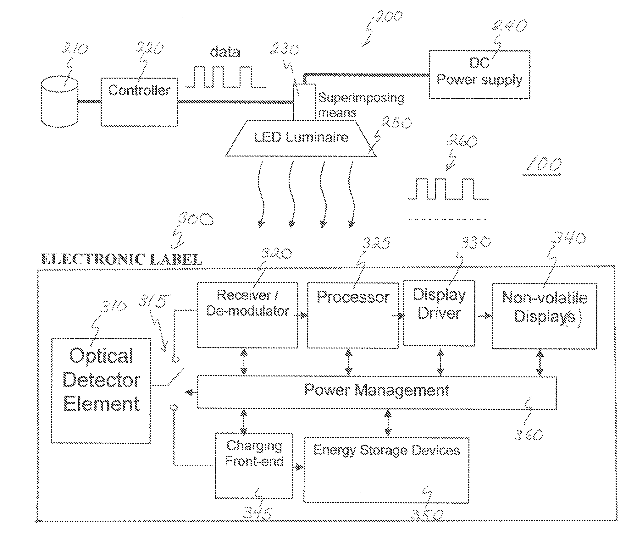
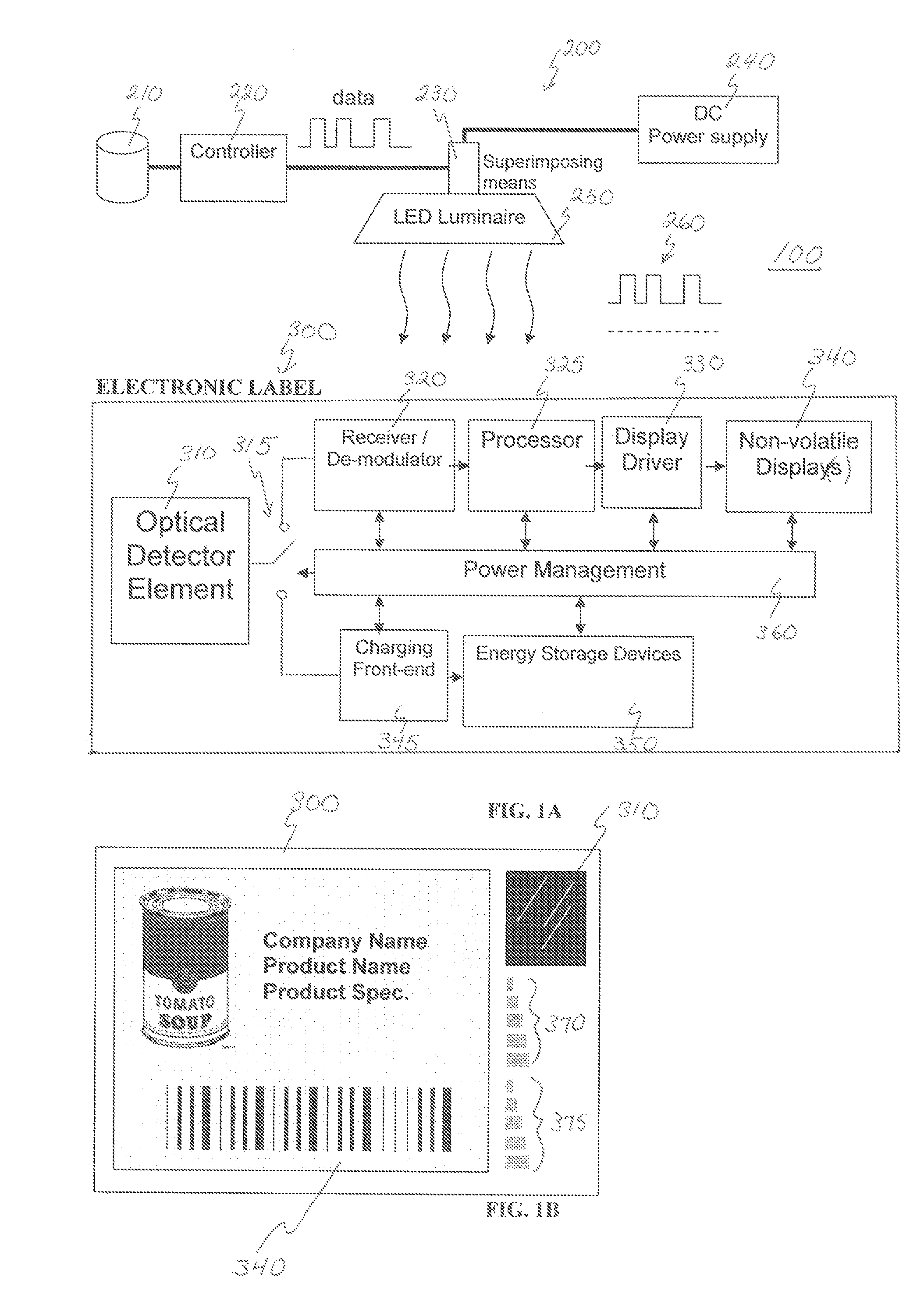
[0017]Turning now to the drawings in detail, FIG. 1A schematically depicts an overview of an electronic label system 100 according to the present invention. System 100 includes optical signal source 200 and electronic label 300 for receiving the optical signals from source 200. Optical signal source 200 includes data source 210 and controller 220 for creating a modulated data signal to be sent to superimposing element 230. In connection with DC power supply 240, superimposing element 230 creates a modulated power supply signal to power a light source 250. In one embodiment, light source 250 is an LED array, such that an intensity-modulated optical signal 260 is created. A variety of known intensity-modulation techniques may be used to modulate the optical signal including, but not limited to, binary OOK, multi-level PAM, PWM, and PSK. The wavelength(s) of the optical signals emitted by LED array are preferably selected to be within the range of approximately 450 nm to 900 nm althoug...


PUM


Abstract

An electronic label system is provided which includes a data source having information to be displayed by an electronic label. An optical source such as an LED array broadcasts optical signals modulated with the data source data to plural electronic labels. Each electronic label has an optical receiver which receives the modulated optical signals and also receives unmodulated optical signals to supply power to an energy storage device. A mode switch switches the optical receiver between a signal reception mode and an energy storage device power-supplying mode. One or more bistable displays display the data received from the modulated optical signals. Through the use of bistable displays, the power consumption of the electronic label is greatly reduced while use of a single receiving element for receiving both the signal light and power storage light reduces the number of components needed to assemble the electronic label, thus reducing cost.

Description

FIELD OF THE INVENTION[0001]The present invention relates to electronic labels that display information and, more particularly, to low-power consumption electronic labels that are powered by ambient light and are remotely-controllable.BACKGROUND[0002]In warehouses, retail establishments, shipping centers and other places where products are stored, it is convenient to affix electronic labels on or adjacent to products to identify the product and include other important information such as price, product destination, country of origin, etc. Because the information displayed on electronic labels often needs to be changed or updated, it is particularly useful to be able to remotely control the information displayed on the electronic label.[0003]Various electronic label systems have been proposed. For example, U.S. Pat. No. 6,715,676 describes an electronic price label in which an infrared LED array is used to transmit information to a receiver on the label. This receiver is an IR-filter...

Claims


Application Information

Patent Timeline
IPC IPC(8): G06F17/00
CPCG06F3/147G09G2330/023G09G2380/14G09G2380/04G09G2370/18
Inventor HUNG, WAILU, MING
Owner HONG KONG APPLIED SCI & TECH RES INST
Why Eureka
Try Eureka