System and method for detecting fault in an ac machine

Active Publication Date: 2012-01-05
EATON INTELLIGENT POWER LIMITED
View PDF8 Cites 47 Cited by
  • Summary
  • Abstract
  • Description
  • Claims
  • Application Information

AI Technical Summary

Problems solved by technology

Specifically, motor faults typically result from bearing and gearbox failures, stator faults resulting in the opening or shorting of the phase winding, rotor cage failure (e.g., broken rotor bars or end-rings), or air-gap irregularities.
Rotor cage failure is one of the most common failures on medium and high voltage large induction machines.
The mechanical performance of the rotor cage decays rapidly due to the high thermal stresses on the rotor cage during motor startup, which can cause thermal expansion and thus mechanical stresses, magnetic stresses caused by electromagnetic forces and unbalanced magnetic pull, dynamic stresses that result from the high rotating torque during operation, environmental stresses due to contamination and abrasion of rotor material, as well as mechanical stresses due to loose laminations, etc.
As the mechanical performance of the rotor cage degrades, breakage of the rotor bar or end ring may occur.
When rotor cage failure occurs, the performance of the overall motor system largely degrades, often resulting in output torque/speed oscillation, possibly stator/rotor rub, and eventually catastrophic motor system breakdown.
Motor faults not only lead to the repair or replacement of the individual motor, but also cause financial losses due to long lead times for repairs and

Method used


Image

  • System and method for detecting fault in an ac machine
  • System and method for detecting fault in an ac machine
  • System and method for detecting fault in an ac machine

Examples


Embodiment Construction

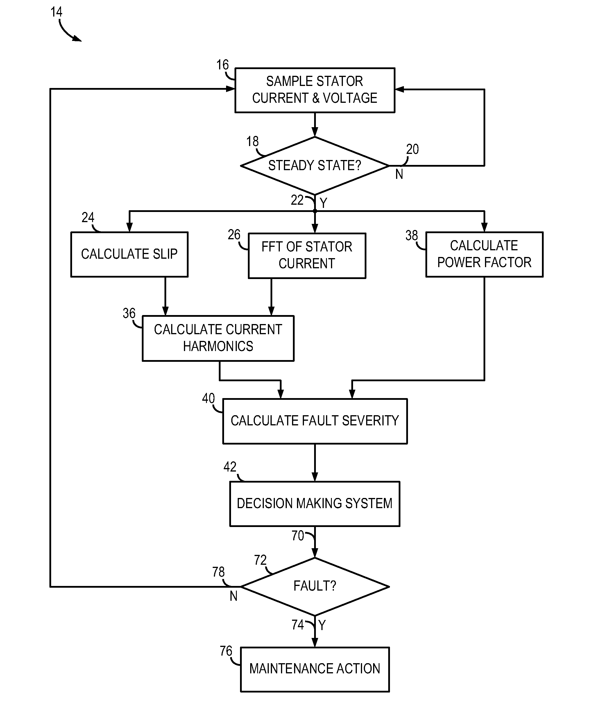
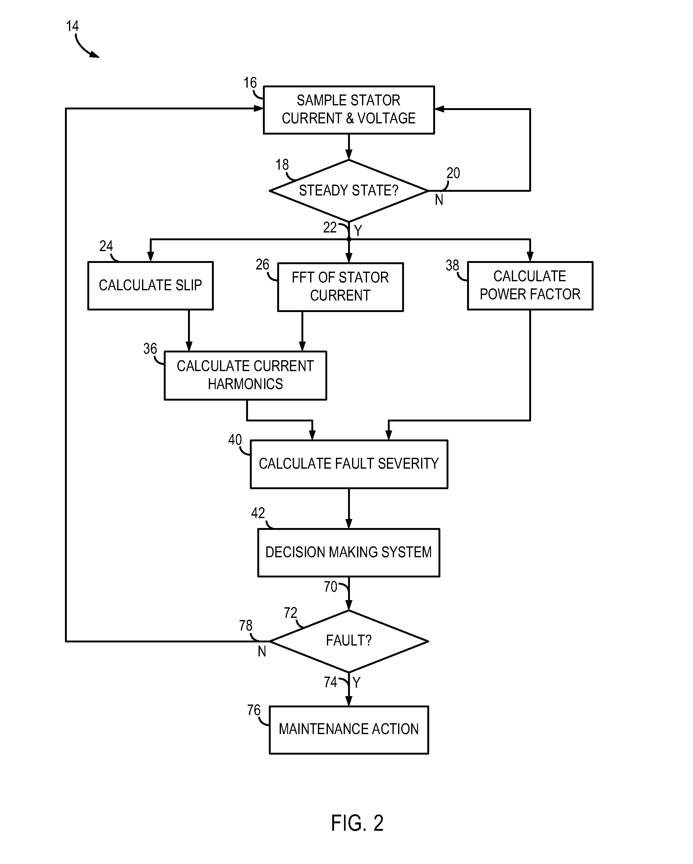
[0028]Several embodiments of the invention are set forth that relate to a system and method of detecting a rotor cage fault in an AC induction machine. The system monitors current and voltage and performs a current analysis to generate a fault index indicative of the severity of a rotor fault condition.

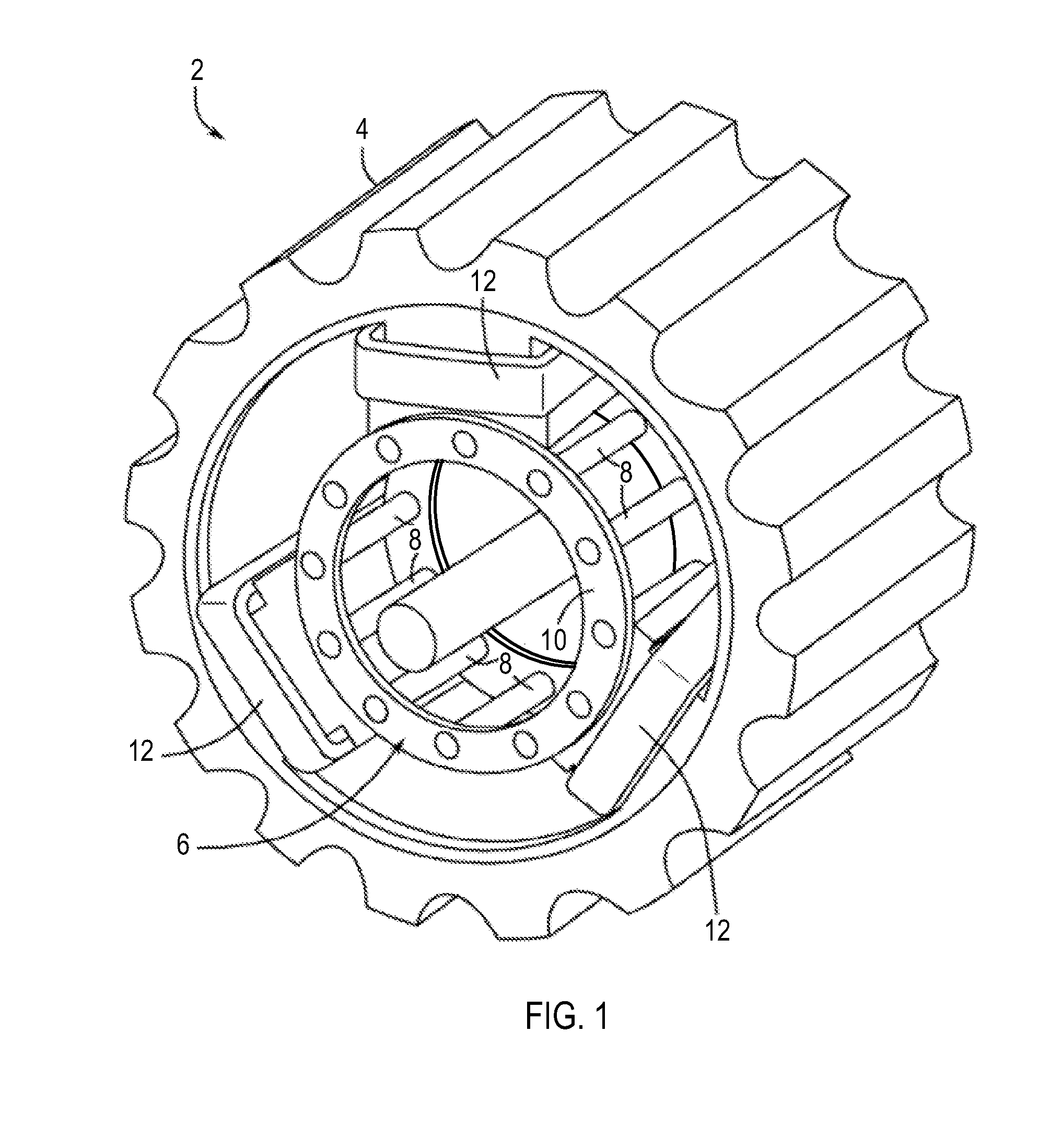
[0029]FIG. 1 illustrates an AC induction machine 2 comprising a stator 4 and a rotor cage assembly 6. AC induction machine 2 may be a motor or generator, according to various embodiments of the invention. Rotor assembly 6 includes a number of rotor bars 8 coupled to an end-ring 10. In operation, current flows through stator windings 12 creating a magnetic field that induces current flow through rotor bars 8. When a rotor failure occurs, such as a broken rotor bar or broken end-ring, current cannot flow through the broken rotor component, which results in an unbalanced rotor flux. The unbalanced rotor flux, along with speed and torque oscillation caused by the broken rotor component, i...


PUM


Abstract

A system and method for detecting a rotor fault condition in an AC induction machine is disclosed. The system includes a processor programmed to receive voltage and current data from an AC induction machine, generate a current frequency spectrum from the current data, and identify rotor-fault related harmonics in the current frequency spectrum. The processor is also programmed to calculate a fault severity indicator using the voltage and current data, identified rotor-fault related harmonics, and motor specifications, analyze the fault severity indicator to determine a possibility of rotor fault. The processor generates an alert based on the possibility of rotor fault.

Description

BACKGROUND OF THE INVENTION[0001]The present invention relates generally to induction machines and, more particularly, to a system and method for detecting fault in an AC induction machine.[0002]Induction machines are widely used in industry for their cost-efficient and robust nature. Many applications for this “workhorse” of industry are fan and pump industrial applications. For example, in a typical integrated paper mill, low voltage and medium voltage motors may comprise nearly 70% of all driven electrical loads. Due to the prevalence of these motors in industry, it is paramount that the induction motor be reliable. Industry reliability surveys suggest that motor failures typically fall into one of four major categories. Specifically, motor faults typically result from bearing and gearbox failures, stator faults resulting in the opening or shorting of the phase winding, rotor cage failure (e.g., broken rotor bars or end-rings), or air-gap irregularities.[0003]Rotor cage failure i...

Claims


Application Information

Patent Timeline
IPC IPC(8): G01R31/02
CPCG01R31/343
Inventor ZHANG, PINJIALU, BINHABETLER, THOMAS G.
Owner EATON INTELLIGENT POWER LIMITED
Why Eureka
Try Eureka