Method and apparatus for detecting position

a technology of position detection and method, applied in the direction of satellite radio beaconing, measurement devices, instruments, etc., can solve the problems of wasteful power consumption of gps receivers, power supply interruptions, and gps receivers not implementing positioning, so as to achieve efficient suppression of power consumed by gps receivers

Active Publication Date: 2012-01-05
JVC KENWOOD CORP A CORP OF JAPAN
View PDF3 Cites 4 Cited by
  • Summary
  • Abstract
  • Description
  • Claims
  • Application Information

AI Technical Summary

Benefits of technology

[0018]This invention is advantageous in that a GPS receiver properly implements positioning while power consumed by the GPS receiver is efficiently suppressed.

Problems solved by technology

Accordingly, power is wastefully consumed by the GPS receiver.
In the event that the GPS receiver fails to complete positioning within a prescribed time interval, the power supply thereto is forcedly interrupted.
During the forced interruption of the power supply, the GPS receiver does not implement positioning even when normal conditions are restored where the GPS receiver can track at least three GPS satellites.

Method used


Image

  • Method and apparatus for detecting position
  • Method and apparatus for detecting position
  • Method and apparatus for detecting position

Examples


first embodiment

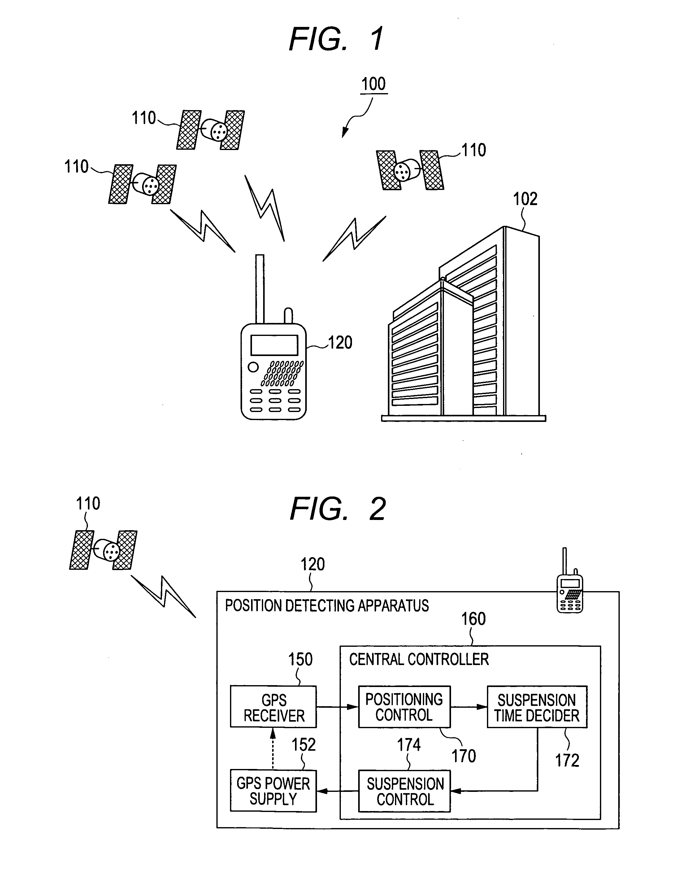
[0030]With reference to FIG. 1, a position detecting system 100 includes a plurality of GPS satellites 110 and a position detecting apparatus 120 according to a first embodiment of this invention.

[0031]Each GPS satellite 110 contains an atomic clock for measuring the time through the use of an atomic or molecular spectral line. The GPS satellite 110 generates a GPS signal having information representative of the time measured by the atomic clock and the position (the in-orbit position) of the satellite 110, and transmits the GPS signal via frequency bands of 1.2 / 1.5 GHz. The time represented by the information in the GPS signal means the time of transmission of the GPS signal from the satellite 110.

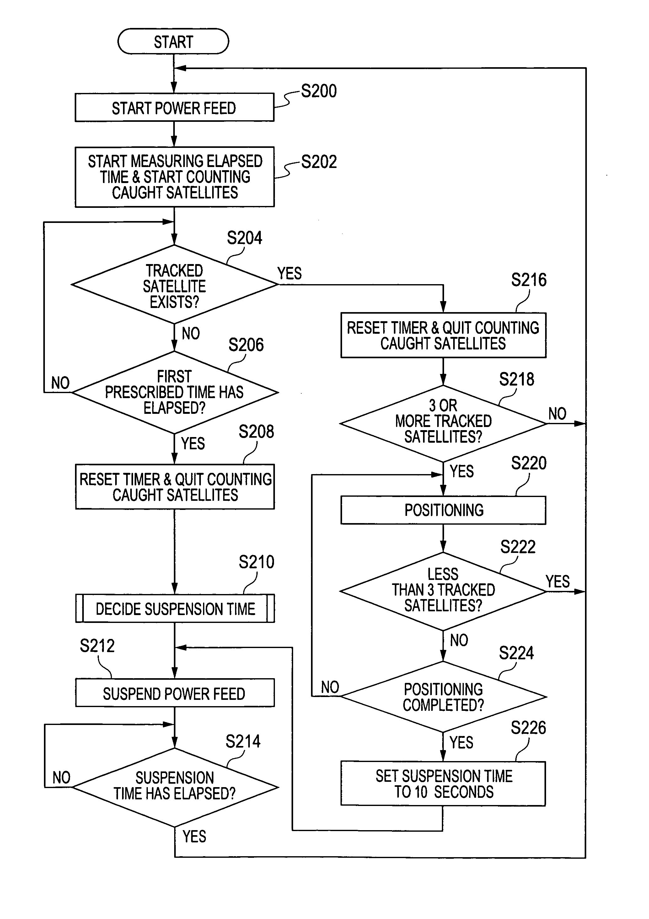
[0032]The position detecting apparatus 120 can receive GPS signals from GPS satellites 110 in view. The case where the position detecting apparatus 120 satisfactorily derives information effective for positioning (position measurement) from received GPS signals is referred to as the case ...

second embodiment

[0086]FIG. 6 shows a position detecting apparatus 320 according to a second embodiment of this invention. The position detecting apparatus 320 is similar to the position detecting apparatus 120 of FIG. 2 except for design changes mentioned hereafter.

[0087]The position detecting apparatus 320 includes a central controller 360 instead of the central controller 160 (see FIG. 2). The central controller 360 may be similar in hardware to the central controller 160. Preferably, a control program for the central controller 360 enables the central controller 360 to perform operation steps and actions mentioned hereafter.

[0088]The control program allows the central controller 360 to serve as the positioning controller 170, a suspension time decider 372, and the suspension controller 174. The suspension time decider 372 replaces the suspension time decider 172 (see FIG. 2). The control program enables the positioning controller 170, the suspension time decider 372, and the suspension controlle...

third embodiment

[0116]FIG. 10 shows a position detecting apparatus 520 according to a third embodiment of this invention. The position detecting apparatus 520 is similar to the position detecting apparatus 120 of FIG. 2 except for design changes mentioned hereafter.

[0117]As shown in FIG. 10, the position detecting apparatus 520 includes the GPS receiver 150, the GPS power supply 152, an operation section 522, a radio communication section 524, an audio output section 526, an audio input section 528, and a central controller 560. The position detecting apparatus 520 is provided with an antenna 502.

[0118]The central controller 560 replaces the central controller 160 (see FIG. 2). The central controller 560 may be similar in hardware to the central controller 160. Preferably, a control program for the central controller 560 enables the central controller 560 to perform operation steps and actions mentioned hereafter.

[0119]The control program allows the central controller 560 to serve as the positionin...


PUM


Abstract

A position detecting apparatus includes a GPS receiver configured to catch one or more of GPS satellites and track one or more of the satellites while receiving a GPS signal or GPS signals from one or more of the satellites. A power supply controllably feeds power to the GPS receiver. A suspension time decider decides a suspension time in accordance with at least one of (1) the number of satellites caught by the GPS receiver and (2) the level of at least one of the received GPS signals, and determines whether or not the lapse of time during which the GPS receiver continues to track no satellite reaches a prescribed time. A suspension controller controls the power supply to suspend the power feed to the GPS receiver during a term equal in length to the decided suspension time in cases where the lapse of time reaches the prescribed time.

Description

BACKGROUND OF THE INVENTION[0001]1. Field of the Invention[0002]This invention relates to a method and an apparatus for detecting a position through the use of GPS (Global Positioning System) satellites.[0003]2. Description of the Related Art[0004]A GPS-based position detecting apparatus includes a GPS receiver for receiving GPS signals from at least three GPS satellites moving around the earth. The GPS receiver derives positing information from the received GPS signals. When information effective for positioning can be derived from the received GPS signals, that is, when the GPS satellites from which the received GPS signals come are worth tracking, the GPS receiver analyzes the received GPS signals in detail and computes the absolute position (the latitude and the longitude) of the apparatus in a plane on the earth from the results of the analyzation.[0005]In the event that the GPS-based position detecting apparatus is in an underground place or shaded from GPS satellites by a bui...

Claims


Application Information

Patent Timeline
Patent Type & Authority Applications(United States)
IPC IPC(8): G01S19/34
CPCG01S19/34
Inventor TACHIGI, KAZUOMI
Owner JVC KENWOOD CORP A CORP OF JAPAN
Why Eureka
Try Eureka