Beam combiner for use in a head-mounted display device and beam splitter

a beam splitter and combiner technology, applied in the field of beam splitter and beam combiner, can solve the problems of difficult production technique, unfavorable image generation, and undesired scattered light, and achieve the effect of simple manufacturing

Active Publication Date: 2012-01-05
TOOZ TECH GMBH
View PDF4 Cites 94 Cited by
  • Summary
  • Abstract
  • Description
  • Claims
  • Application Information

AI Technical Summary

Benefits of technology

[0011]The deflecting elements can be formed at a material boundary surface (which can be flat or curved) of the body. A particularly simple manufacture is thus possible, e.g. by means of diamond milling. Furthermore, a production by moulding and casting methods is possible.

Problems solved by technology

However, the production technique is difficult, in particular if the light of the generated image is guided in the glass and the glass is curved.
However, this often disadvantageously involves undesired scattered light due to additional diffraction orders.
Furthermore, such a grating is often only very narrow-band, with the result that the generated image can be only monochrome.

Method used


Image

  • Beam combiner for use in a head-mounted display device and beam splitter
  • Beam combiner for use in a head-mounted display device and beam splitter
  • Beam combiner for use in a head-mounted display device and beam splitter

Examples


Embodiment Construction

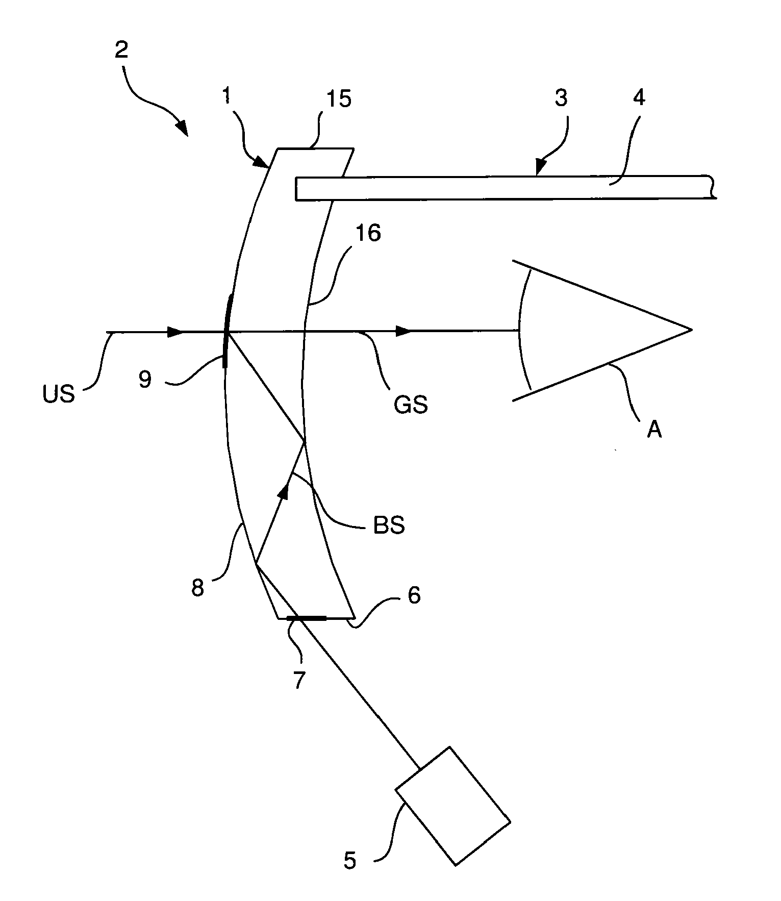
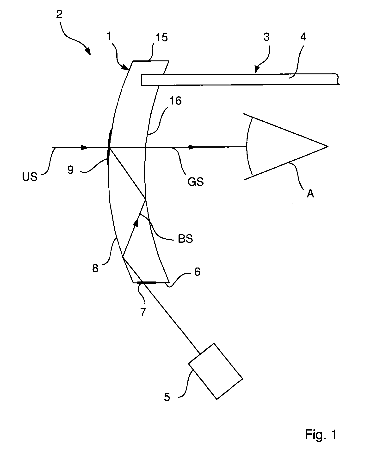
[0064]In the embodiment shown in FIGS. 1 to 3, the beam combiner 1 according to the invention is formed as a multifunction glass of a display device 2 which comprises a holding device 3 that can be fitted onto the head of a user in the form of a glasses frame, wherein only one side arm 4 is drawn in schematically in FIG. 1.

[0065]The beam combiner 1 is attached to the holding device 3 such that when the holding device 3 is fitted onto the head it is arranged in the manner of a glasses lens in front of an eye A of the user. The user can perceive the surroundings through the beam combiner 1.

[0066]The display device 2 furthermore comprises an image-generating module 5 with which an image is generated which is presented to the user of the display device 2 superimposed on the surroundings perceptible for the user through the multifunction glass 1 when the user is wearing the display device on his head.

[0067]For this, the multifunction glass 1 has a coupling-in section 7 on its underside 6...


PUM


Abstract

A beam combiner for combining a first beam cluster with a second beam cluster that is not parallel to the first, to form a common beam cluster. The beam combiner includes a transparent body for the first beam cluster, which has a superimposition region that is encountered by the first beam cluster as it passes through the body. The superimposition region is split into a first section and a second section. Only the first section formed from interspaced reflective and / or refractive deflection elements causes a deflection of the second beam cluster by reflection and / or refraction, such that the first beam cluster forms the common beam cluster with the deflected second beam cluster once it has left the body.

Description

PRIORITY CLAIM[0001]The present application is a National Phase entry of PCT Application No. PCT / EP2010 / 052418, filed Feb. 25, 2010, which claims priority from German Application Number 102009010537.9, filed Feb. 25, 2009, the disclosures of which are hereby incorporated by reference herein in their entirety.FIELD OF THE INVENTION[0002]The present invention relates to a beam combiner and a beam splitter.BACKGROUND[0003]A beam combiner is needed e.g. in a display device that can be fitted onto the head of a user, in order to be able to present to the user a generated image superimposed on the perceptible surroundings. The beam combiner is often formed as a curved spectacle lens in this case.[0004]It is known to realize a beam combining through a semi-transparent mirror. However, the production technique is difficult, in particular if the light of the generated image is guided in the glass and the glass is curved.[0005]Furthermore, a beam combining can be effected by means of an optic...

Claims


Application Information

Patent Timeline
Patent Type & Authority Applications(United States)
IPC IPC(8): G02B27/01
CPCG02B3/08G02B5/02G02B2027/0178G02B27/143G02B27/0172
Inventor DOBSCHAL, HANS-JUERGENRUDOLPH, GUENTERLINDIG, KARSTEN
Owner TOOZ TECH GMBH
Why Eureka
Try Eureka