Metalized film capacitor

a film capacitor and metal film technology, applied in the direction of wound capacitors, fixed capacitor details, fixed capacitors, etc., can solve the problems of small energy of the split electrode, insufficient self-restoring function, and decrease in capacitor safety, so as to achieve good safety-keeping performance

Active Publication Date: 2012-01-05
NICHICON CORP
View PDF5 Cites 12 Cited by
  • Summary
  • Abstract
  • Description
  • Claims
  • Application Information

AI Technical Summary

Benefits of technology

[0043]It is preferred to arrange, as the small split electrode section, two split electrode sections of a first small split electrode section and a second small split electrode section, and arrange the large split electrode section between the first and second small split electrode sections and adjacently thereto in the width direction of the metalized film. According to this structure, even when the dielectric body is deteriorated by heat, voltage or some other in the first or second small split electrode section so that, over some of the small split electrodes, their fuses act, the electric current path therein can be prevented from being extremely disturbed. In other words, if the non-split electrode section is arranged between the first and second small split electrode sections to be adjacent thereto in the film width direction, it is feared that the electric current path therein is extremely disturbed when over some of the small split electrodes their fuses act; this is because no insulating slits for dividing the vapor-deposited electrode are present in the non-split electrode section. As a result, the capacitor may undergo an extreme rise in dielectric loss and equivalent series resistance. Against this, the large split electrode section is arranged between the first and second small split electrode sections to be adjacent thereto in the metalized film width direction, thereby making it possible that the insulating slits formed in the large split electrode section regulate one or more electric current paths to prevent the electric current path from being extremely disturbed.
[0044]In the metalized film capacitor including the capacitor element made of a metalized film pair in which two of the metalized films are stacked onto each other, it is preferred that the electrode surfaces of the whole of the large split electrode section and the non-split electrode section formed in one of the paired metalized films are opposed to the small split electrode section formed in the other metalized film. According to this structure, even when one of the paired metalized films undergoes dielectric breakdown, which is caused beyond the self-restoring function (self-healing function) of the metalized film, in its large split electrode section or non-split electrode section, a sufficient electric current flows from the large split electrode, this large split electrode being larger in electrode area th

Problems solved by technology

However, at a high temperature and a high pressure, the number of dielectric broken sites increases so that the self-restoring function is not sufficiently obtained.
However, when the split electrodes are made too fine, the energy of the split electrodes becomes small.
Thus, when the split electrodes undergo dielectric breakdown, the fuses come not to act easily so that the s

Method used


Image

  • Metalized film capacitor
  • Metalized film capacitor
  • Metalized film capacitor

Examples


example 4

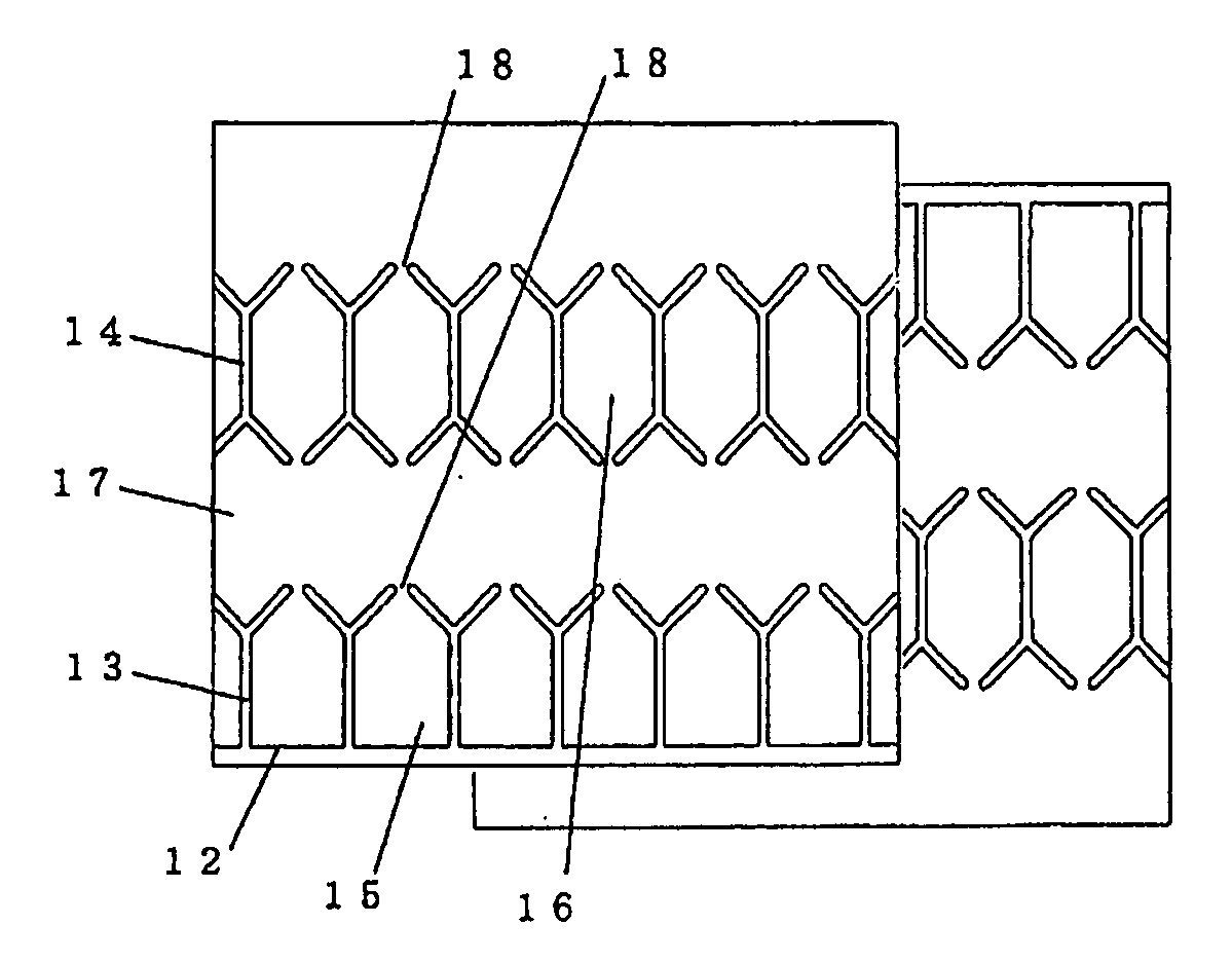
“(Two-Opposed-Row) Y-Shaped” Insulating Slits in FIG. 5; Pitch: 6.0 mm

[0092]In a metalized film capacitor illustrated in FIG. 5, Y-shaped insulating slits 13 are arranged at the insulating margin 12 side of one out of two metalized films and at a regular pitch in the longitudinal direction. Base end regions of the Y-shaped insulating slits 13 are jointed to the insulating margin 12. In a split electrode section having the Y-shaped insulating slits 13 arranged at the insulating margin 12 side as described just above (this section corresponds to the “insulating margin side split electrode section”), an vapor-deposited electrode is divided into plural segments by the Y-shaped insulating slits 13, and split electrodes 15 are formed between the Y-shaped insulating slits 13. An electrode region sandwiched between an end region (at the metallikon-connection section 10 side) of one of any adjacent two of the Y-shaped insulating slits 13 and an end region (at the metallikon-connection sectio...

example 1

PRIOR ART EXAMPLE 1

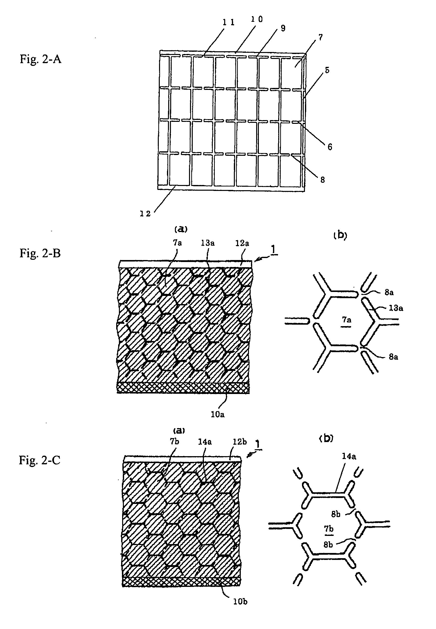
Rectangular Insulating Slits in FIG. 2-A; Pitch: 6.0 mm

[0100]A metalized film capacitor was produced under the same conditions as in Example 1 except that the pitch of the insulating slits 5 for dividing the split electrodes 7 of the metalized film illustrated in FIG. 2-A from each other in the form of rectangles in the longitudinal direction was set to 6.0 mm; the area of the split electrodes was made equal to that of the split electrodes 16 in FIG. 4; and the width of the fuses 8 and 11 for connecting the split electrodes to each other was set to 0.2 mm.

example 2

PRIOR ART EXAMPLE 2

Formation of Honeycombed Split Electrodes by Use of Y-Shaped Insulating Slits in FIG. 2-B

[0101]A metalized film capacitor was produced under the same conditions as in Example 1 except that the capacitor was permitted to have the honeycombed split electrodes 7a of the metalized film illustrated in FIG. 2-B; the area of the split electrodes was made equal to that of the split electrodes 16 in FIG. 4; and the width of the fuses 8a for connecting the split electrodes to each other was set to 0.2 mm.


PUM


Abstract

Disclosed is a metalized film capacitor having excellent safety preservation ability and an excellent withstand voltage at high temperatures. This capacitor has a structure for which a split electrode section wherein a split electrode is formed by spliting a metalized film along the longitudinal direction by means of plural insulating slits, and a non-split electrode section for which a vapor-deposited electrode is continuous in the longitudinal direction, are arranged alternately in the film width direction of the metalized film, with each split electrode being connected to the non-split electrode section by a fuse formed between the ends of adjacent insulating slits; and has a structure for which three rows or more of split electrode sections, which are split by means of insulating slits that are aligned in the longitudinal direction of the film, are arranged in the width direction, with each split electrode that forms a split electrode section being connected to an adjacent split electrode by a fuse, and the area of a split electrode in the center of the film being smaller than the area of a split electrode arranged on the outer side.

Description

CROSS REFERENCE TO RELATED APPLICATION[0001]The disclosure of Japanese Patent Applications No. 2009-024624 filed Feb. 5, 2009, No. 2009-085036 filed Mar. 31, 2009, No. 2009-121076 filed May 19, 2009, and No. 2009-197675 filed Aug. 28, 2009 including specification, drawings and claims is incorporated herein by reference in its entirety.TECHNICAL FIELD[0002]The present invention relates to a metalized film capacitor used for the smoothing or the filter of an inverter circuit for industrial devices, automobiles, and others.BACKGROUND ART[0003]In a metalized film capacitor in the prior art, a metalized film is used in which a metallikon-vicinity vapor-deposited electrode 2 on a polypropylene film 1 illustrated in FIG. 1 is thickly formed and a non-metallikon-vicinity vapor-deposited electrode 3 thereon is thinly formed by vapor deposition, and an insulating margin 4 is formed at an end region of the film opposed to the metallikon. When the polypropylene film undergoes dielectric breakdo...

Claims


Application Information

Patent Timeline
IPC IPC(8): H01G4/30H01G4/005
CPCH01G4/012H01G4/145H01G4/18H01G4/015H01G4/32H01G4/38
Inventor TAKAGAKI, KOJI
Owner NICHICON CORP
Why Eureka
Try Eureka