Adjusting Method For Recording Condition And Optical Disc Device

a technology of optical disc and recording condition, which is applied in the field of adjustment method of recording condition and optical disc device, can solve the problems of large bit error or byte error, and achieve the effect of reducing the circuitry used in this invention

Inactive Publication Date: 2012-01-05
KONINKLJIJKE PHILIPS NV
View PDF1 Cites 6 Cited by
  • Summary
  • Abstract
  • Description
  • Claims
  • Application Information

AI Technical Summary

Benefits of technology

[0046]According to this invention, since the achievement of a large capacity of more than 30 GB is aimed for, it is assumed in the following description of this specification that the minimum run length of the modulation code is 2T. Further, as described above, since the experimental results indicate that the SbER used in the case where up to two 2T continue, coincides well with the bit error rate, it is assumed that SbER is used as the index for evaluating the quality of reproduced signal when the evaluation index for record adjustment according to this invention is discussed. The index for probabilistically evaluating the quality of reproduced signal on the basis of the Euclidean distance between the target signal and the reproduced signal, or the index for directly evaluating bit error rates can yield a good result if the recording condition is adjusted according to this invention.
[0077]The affinity to the evaluation bit arrays used for evaluating the quality of reproduced signal in the calculation of SbER will now be described. The techniques for evaluating reproduced signals disclosed in the patent documents 1, 3 and 4 employ different constitutions but include in common the process of searching / extracting the first most likely evaluation bit array from among binary bit arrays outputted from the PRML decoder. The length M of the evaluation bit array can be generalized to give the equation M=2N−1+2N2T, by using the constraint length N in the PRML procedure and the number N2T of continuous 2T patterns contained in the evaluation bit array. Here, N2T denotes an integer such as 0, 1, 2, . . . . According to the notation described above, N2T=0, 1, 2 correspond to an edge shift, a 2T shift and a 2T knock-on, respectively. Further, when N2T is 0, 1, 2, 3, 4, 5 and 6, the corresponding Hamming distances are 1, 2, 3, 4, 5, 6 and 7, respectively, and the Hamming distance between the evaluation bit arrays of the patterns A and B is (N2T+1). The evaluation bit array can be easily enumerated from among 2M bit arrays through the mechanical operations of extracting the relationship between the first most likely evaluation bit array and the second evaluation bit array corresponding to the target signal that makes minimum the Euclidean distance from the target signal corresponding to the first evaluation bit array.
[0082]In this way, the ordered representation of each evaluation bit array enables the relationship between the index for evaluating the quality of reproduced signal and this invention to be simplified and also the scale of circuitry used in this invention to be reduced.
[0092]FIG. 22 shows in block diagram the configuration of such a circuit for adjusting recording condition. In FIG. 22, the read-out signal 51, which has been read out from an optical disc medium and passed through an analog filter not shown in the figure, is converted to a digital signal having 6˜8 bits by an A / D converter 21, equalized by an automatic equalizer 22, and binarized by a PRML decoder 23 to be output as a binary bit array 52. A circuit 30 for evaluating the quality of the signal for adjusting the write condition comprises edge evaluators 40, 41 and 42; a selector 60; a write pulse evaluation table 35; and a timing adjuster 36. The edge evaluator 40 performs the evaluation of the edge shift along time axis with respect to each edge in a CD / DVD system; the edge evaluator 41 performs the evaluation of V-SEAT for BD; and the edge evaluator 42 performs the evaluation of L-SEAT for high-density BD. Each edge evaluator calculates the amount of edge shift, the extended edge shift or the SNR factor with respect to each edge. The selector 60 selects the outputs of the edge evaluators depending on the kinds of discs subjected to write / read operation. The write pulse evaluation table 35 synchronizes the binarized bit array 52 with the edge evaluation index outputted from the edge evaluator, performs the classification of bit patterns in accordance with adaptive recording pulses, allocates the bit patterns into, for example, a 4×4 table, and calculates the average or standard deviation per table component. A CPU 140 refers to the result obtained by the write pulse evaluation table 35 and processes the adjustment of the respective parameters of the adaptive recording pulses. With this configuration described above, the parallel adjustments of parameters of the adaptive recording pulses becomes possible for different kinds of optical disc media. Accordingly, the adjustment of condition for write pulses can be achieved in a short period of time and in a limited test write area, in comparison with the method that uses a single evaluation index for read-out signal.
[0093]In this way, it has become possible to provide the evaluation index for adjusting the recording condition, the adjusting method for recording condition and the optical disc device using the evaluation index and the adjusting method, which, regarding the adjustment of write condition corresponding to high-density recording with recording capacity of more than 30 GB per disc surface based on BD systems, can solve the above described problems peculiar to the conventional techniques and which can (1) enjoy the high compatibility of the reproduction of data recorded in accordance with the result of the adjustment, (2) guarantee that the quality of the data recorded in accordance with the result of the adjustment is sufficiently good when it is measured in terms of the evaluation index for reproduced signal such as SbER, and (3) adjust the condition of the adaptive recording pulse in a short period of time. The gist of this invention is the provision of the adjusting method for recording condition and the optical disc device using this method, wherein when reproduced signals are evaluated by using the target signals having more than three Hamming distances (corresponding to =1, 2 and 3) with respect to an optical disc using recorded marks whose shortest run length is equal to 2T as in BD, the quality of the interested edge is evaluated in accordance with the method for evaluating extended edge shifts at respective time instants or the method for evaluating the average of distributions of independently calculated Euclidean distance differences; and the recording condition is adjusted on the basis of the result of the evaluation.

Problems solved by technology

Regarding write-once optical discs, for example, in the case where data are recorded in and reproduced from plural locations in the disc with the recording condition varied, even the best recording condition for the former method may cause a large bit error or byte error if fingerprints overlie the recorded data.

Method used


Image

  • Adjusting Method For Recording Condition And Optical Disc Device
  • Adjusting Method For Recording Condition And Optical Disc Device
  • Adjusting Method For Recording Condition And Optical Disc Device

Examples


Embodiment Construction

[0139]The adjusting method for recording condition and the optical disc device according to this invention will now be described by way of embodiment in reference to the attached drawings.

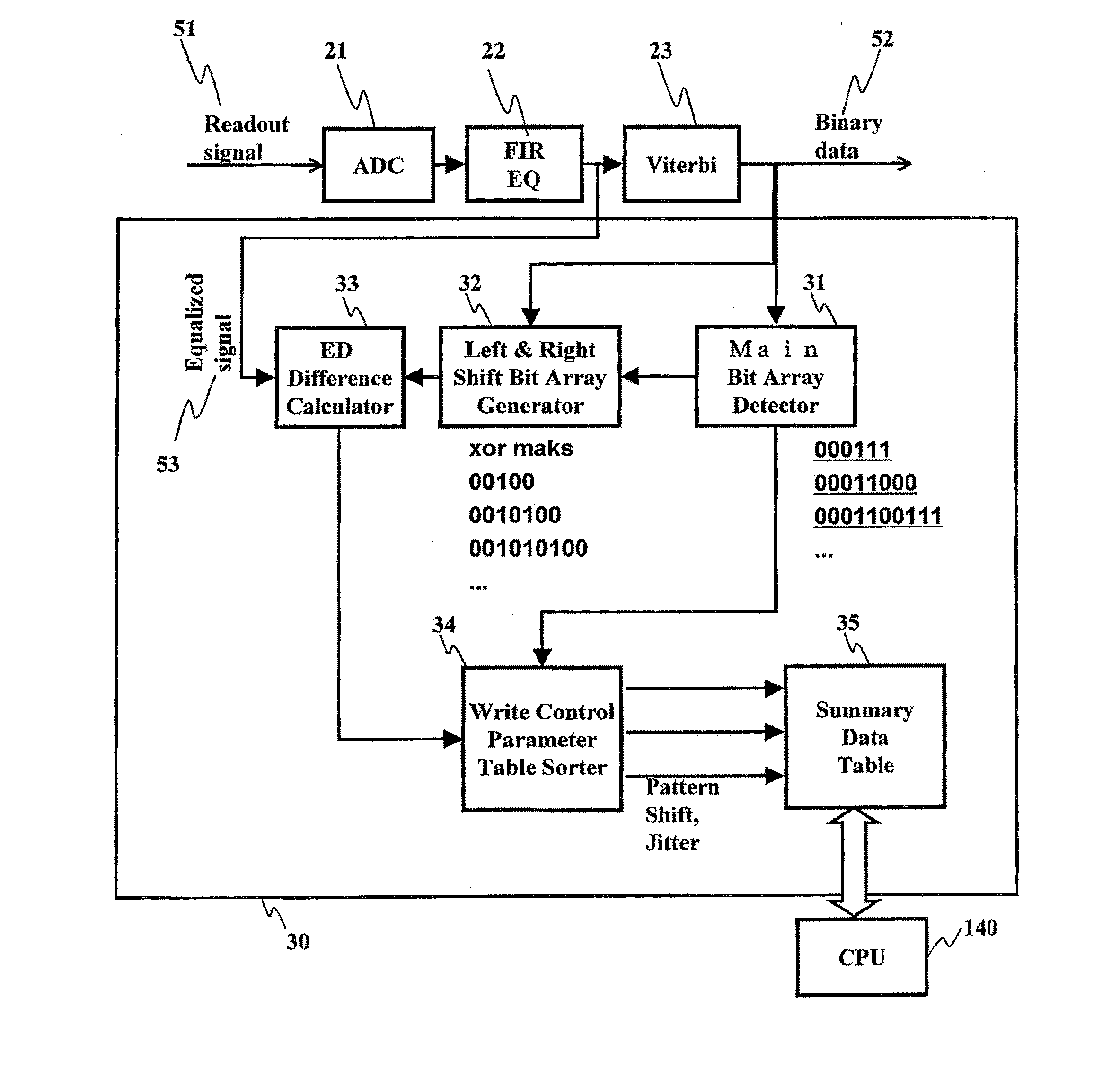
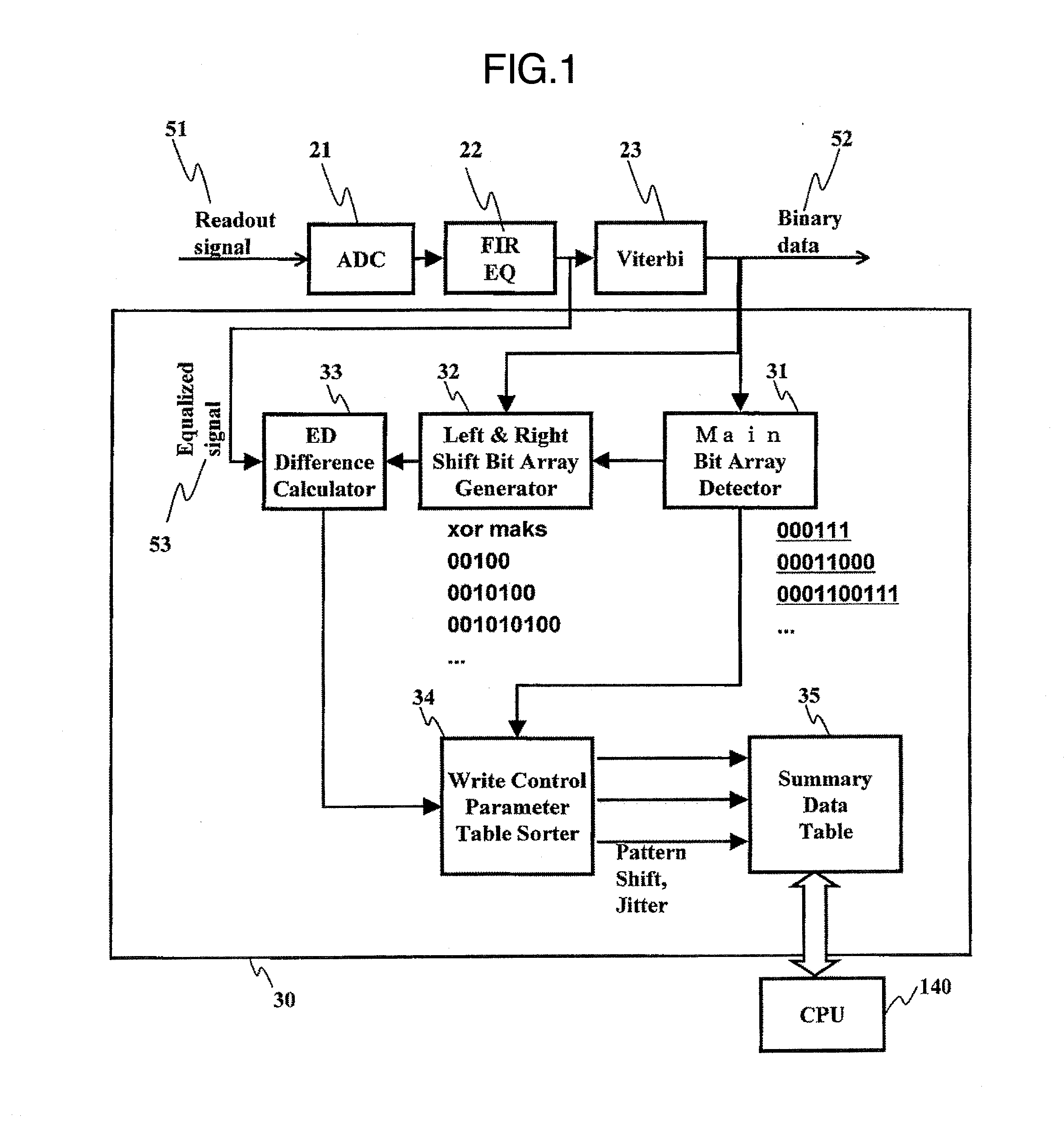
[0140]FIG. 23 is another embodiment of the table listing main bit arrays for edge evaluation according to this invention. The listed main bit arrays are for the case where N2T is equal to 3. There are 20 main bit arrays listed in total. In each main bit array, the underlined bit corresponds to an interested edge. The main bit arrays No. 1˜12 are the same as those listed in the table shown in FIG. 18. The main bit arrays No. 13˜20 correspond to the case where the continuous 2T count is 3. As described above, there is only one evaluation bit array that is the secondary likelihood bit array, among main bit arrays listed in FIG. 15 or FIG. 16. Accordingly, even in case of such a binarized bit array with N2T=3 as “0000011001100”, the quality of reproduced signal is evaluated by regarding the bit array “...


PUM

PropertyMeasurementUnit
wave lengthaaaaaaaaaa
thicknessaaaaaaaaaa
widthaaaaaaaaaa

Abstract

An optical disc device and an adjusting method for a recording condition for use with the optical disc device that records data into an optical disc medium by using codes whose shortest run length is 2T and reproduces the recorded data by using an adaptive equalizing procedure and a PRML procedure, wherein the recording condition is so adjusted that a reproduced signal with desired quality can be obtained, by using, as the adaptive equalizing procedure, a procedure in which a tap coefficient Cn is set to a value obtained by averaging values of a tap coefficient an renewed by a LMS method, located symmetrically with each other along the time axis.

Description

CROSS REFERENCE TO RELATED APPLICATION[0001]This application is a continuation of U.S. application Ser. No. 12 / 569,021, filed Sep. 29, 2009, the contents of which are incorporated herein by reference.INCORPORATION BY REFERENCE[0002]The present application claims priority from Japanese application JP2009-097590 filed on Apr. 14, 2009, the content of which is hereby incorporated by reference into this application.FIELD OF THE INVENTION[0003]This invention relates to a method for adjusting recording condition in recording information in an optical disc medium on which recorded marks are formed that have a physical property different from the physical property of that part of the optical disc medium which is other than the recorded marks, and also relates to an optical disc device using the adjusting method.BACKGROUND OF THE INVENTION[0004]Optical disc media now widely available include CD-R / RW, DVD-RAM, DVD±R / Rw, BD, etc., and some of them have two data layers. Optical disc devices ada...

Claims


Application Information

Patent Timeline
Patent Type & Authority Applications(United States)
IPC IPC(8): G11B20/10
CPCG11B7/0045G11B7/005G11B20/10009G11B20/10046G11B20/10055G11B20/1012G11B2220/2541G11B20/10296G11B20/10481G11B20/1816G11B20/182G11B20/22G11B20/225G11B20/10212
Inventor MINEMURA, HIROYUKIKUROKAWA, TAKAHIRO
Owner KONINKLJIJKE PHILIPS NV
Why Eureka
Try Eureka