Eureka AIR delivers breakthrough ideas for toughest innovation challenges, trusted by R&D personnel around the world.

Wireless microphone

Inactive Publication Date: 2012-01-05
PANASONIC CORP
View PDF6 Cites 7 Cited by
  • Summary
  • Abstract
  • Description
  • Claims
  • Application Information

AI Technical Summary

Benefits of technology

[0008]The present invention is made under the above-described background. An object of the present invention is to provide a wireless microphone that can radiate infrared rays to an area around the mic and that has a simple structure and a small number of components and thus can improve productivity.Means for Solving the Problems

Problems solved by technology

However, in a conventional infrared type mic, as described above, a round board needs to be provided and the structure is complex and the number of components is large, and thus, there is a problem of low productivity.
Hence, the structure is complex and the number of components is large, and moreover, the number of board mounting steps increases and the number of man-hours needed for assembly also increases, resulting in low productivity.

Method used


Image

  • Wireless microphone
  • Wireless microphone
  • Wireless microphone

Examples


Embodiment Construction

[0026]A detailed description of the present invention will be made below. Note that the following detailed description and the accompanying drawings are not intended to limit the invention. Instead, the scope of the invention is defined by the appended claims.

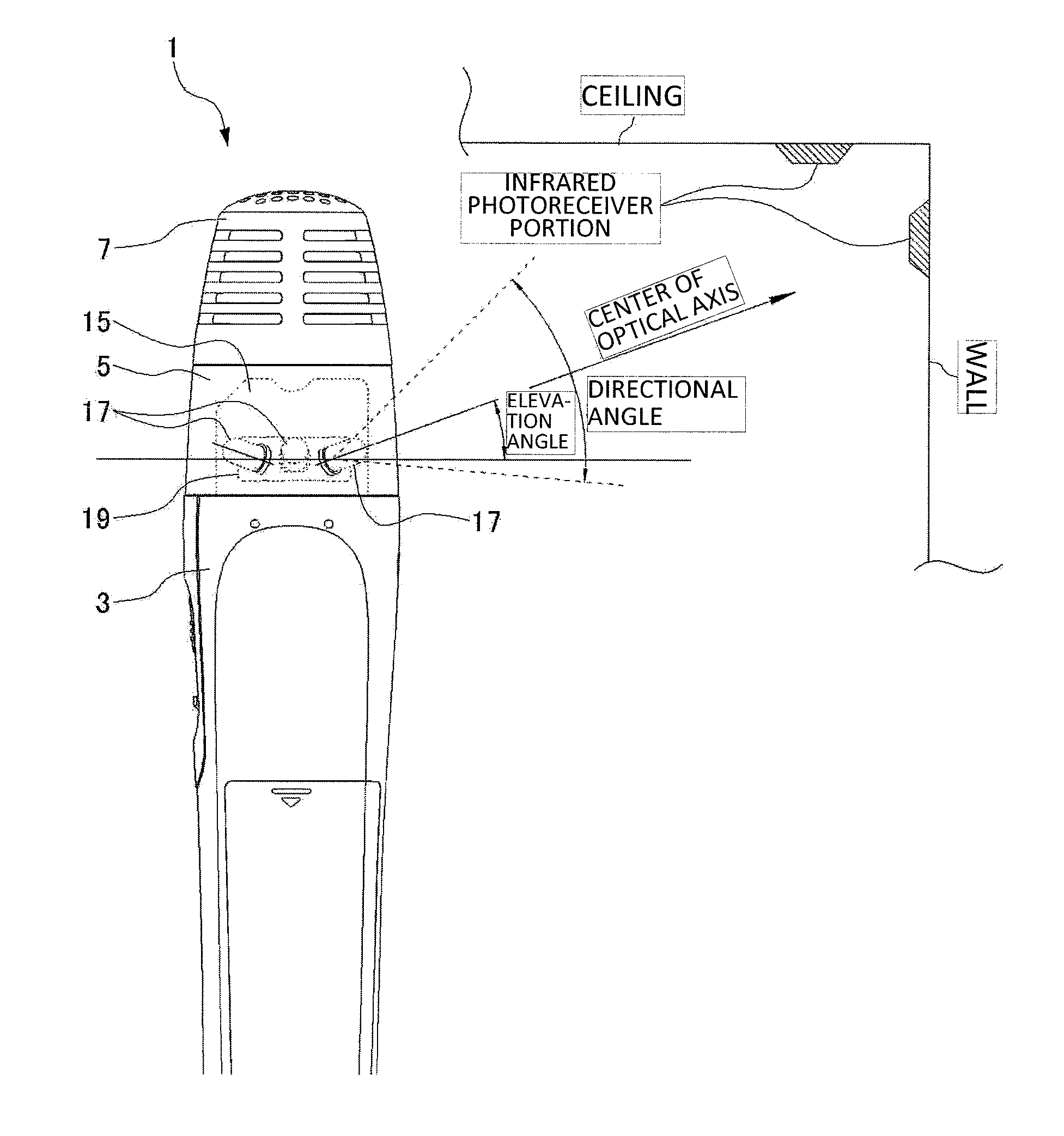
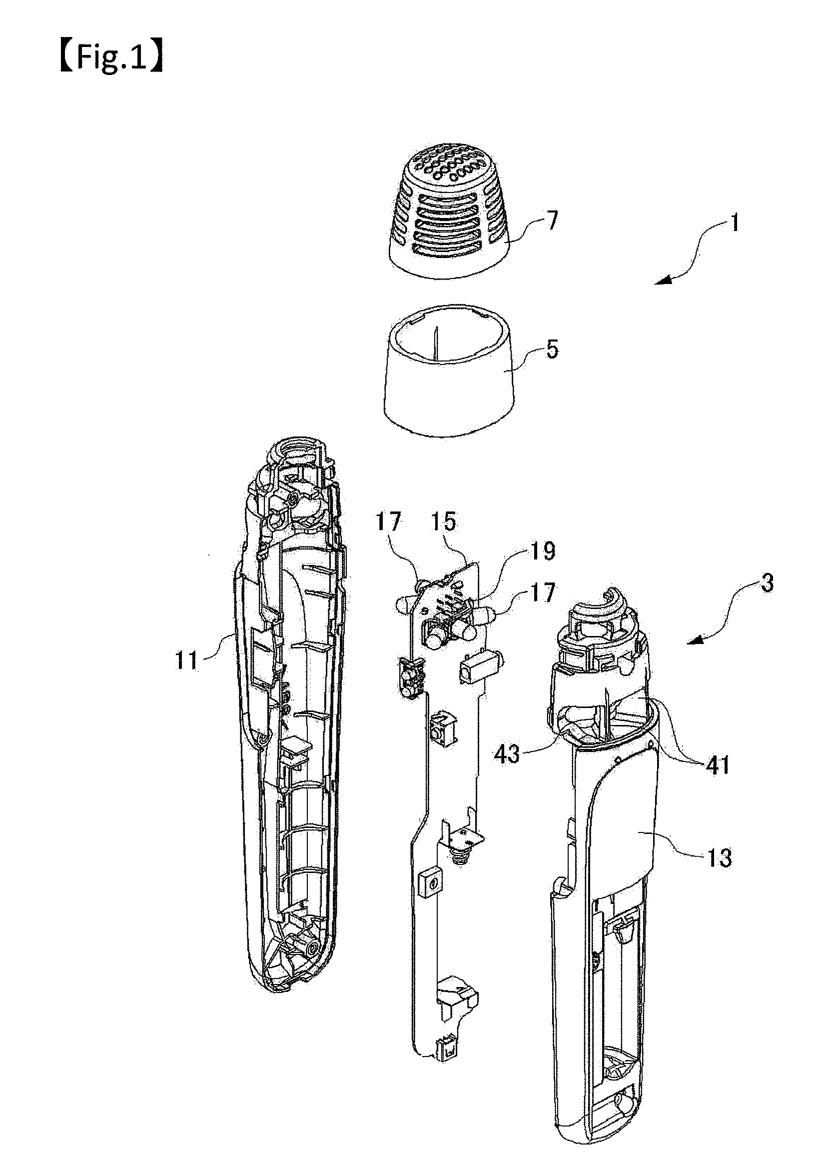
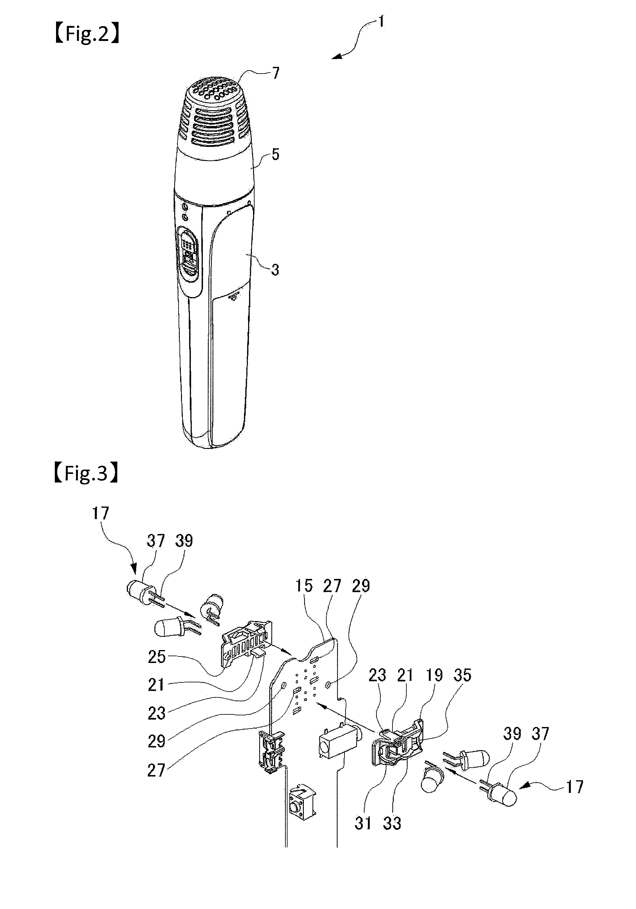
[0027]The present invention is directed to a wireless microphone that transmits audio signals using infrared rays, and a plurality of infrared light emitting devices are attached to a board in the wireless microphone, and at least one of the plurality of infrared light emitting devices is disposed on each side of the board.

[0028]By this configuration, since, by providing infrared light emitting devices on both sides of the board in the wireless microphone, infrared rays can be radiated to an area around the mic, a board provided with infrared light emitting devices does not need to be specially provided and thus a cable or a connector between the boards is not required, either. Accordingly, the structure of the wireless microph...


PUM


Abstract

A wireless microphone transmits audio signals using infrared rays. A plurality of infrared light emitting devices are attached to a board in the wireless microphone, and at least one of the plurality of infrared light emitting devices is disposed on each side of the board. A plurality of infrared light emitting devices may be provided on each side of the board, and the infrared light emitting devices may be disposed radially. Without providing a different dedicated board for the light emitting devices than the board, infrared rays can be radiated to an area around the mic. In this manner, a wireless microphone is provided that can radiate infrared rays to an area around the mic and that has a simple structure and a small number of components and thus can improve productivity.

Description

TECHNICAL FIELD[0001]The present invention relates to a wireless microphone that transmits audio signals using infrared rays.BACKGROUND ART[0002]Conventionally, an infrared type wireless microphone (hereinafter, referred to as a mic) has a tubular case carried by a user, and infrared light emitting devices are included in the case. The infrared light emitting devices are generally light-emitting diodes (LEDs).[0003]To receive a signal from the mic regardless of the directions of the user and mic, infrared rays need to be radiated in all directions, i.e., 360 degree directions. Hence, conventionally, a plurality of light-emitting diodes are mounted on a round board, and furthermore, the leg portions of the light-emitting diodes are bent. By this, the plurality of light-emitting diodes are disposed circularly such that each light-emitting diode faces outward. The round board is accommodated in the tubular case.[0004]In order to avoid the light-emitting diodes from protruding outward f...

Claims


Application Information

Patent Timeline
IPC IPC(8): H04B10/04H04B10/11H04B10/112H04R1/02H04R1/06
CPCH04B10/1141H04B10/116H04R2420/07H04R1/08
Inventor NAKAZAWA, YUKIHIROITOU, TETSUOKAWASAKI, YUUJIYAMAHAI, KEIJIOKUTANI, AKIRA
Owner PANASONIC CORP
Why Eureka
Eureka Blog
Learn More