
Envelope Specific Stimulus Timing

a stimulus timing and envelope technology, applied in the field of cochlear implants, can solve the problems of limited current amplitude, imperfect existing stimulation strategies, and inability to arbitrarily shorten phase durations,

Active Publication Date: 2012-01-05
MED EL ELEKTROMEDIZINISCHE GERAETE GMBH
View PDF1 Cites 41 Cited by
  • Summary
  • Abstract
  • Description
  • Claims
  • Application Information

AI Technical Summary

Benefits of technology

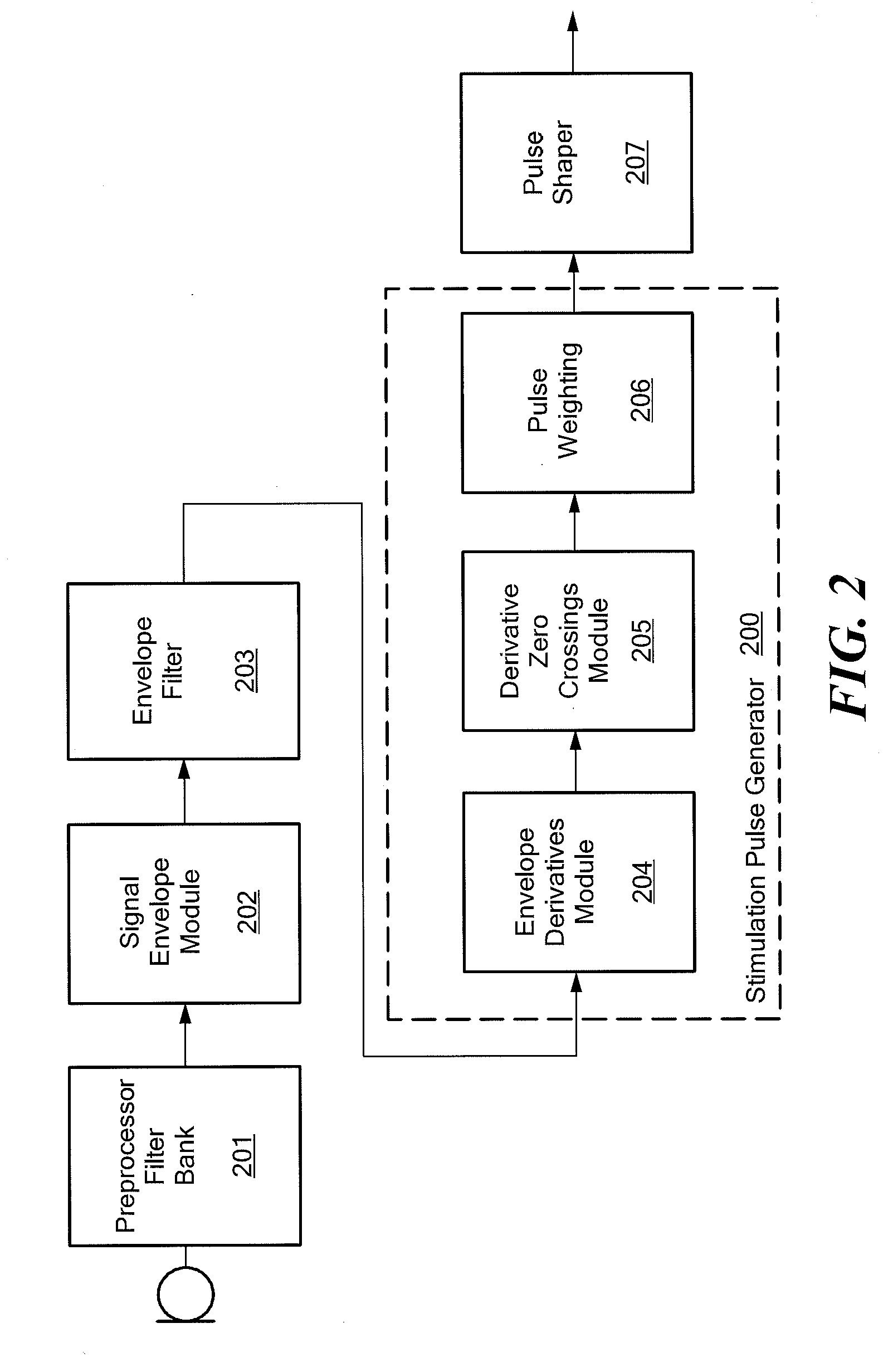
[0017]The stimulation pulse generator may take into account physiological properties of auditory nerve tissue to generate the stimulation event signals. In addition or alternatively, a First Spike Latency (FSL) function may be used to generate the stimulation event signals. There may be a derivative threshold value used to generate the stimulation event signals. The stimulation pulse generator may define the electrode stimulation timings to provide an adaptive delay based on the rate of change of the signal envelope. Stimulation event signals may be generated for all of the stimulation electrodes based on the rate of change of the signal envelope. Or stimulation event signals for some of the stimulation electrodes may be based on a Fine Structure Processing (FSP) function. The stimulation pulse generator may further weight the electrode stimulation amplitudes based on one or more signal features.

Problems solved by technology

The phase duration cannot be chosen arbitrarily short, because the shorter the pulses, the higher the current amplitudes have to be to elicit action potentials in neurons, and current amplitudes are limited for various practical reasons.
It is known that existing stimulation strategies are imperfect.
FSP does provide fine structure information on some of the lower frequency channels, and CIS-like stimulation on the higher channels, but FSP strategies suffer from channel interactions that are enforced by an unbalanced rate-profile: a high rate is applied for CIS-channels, and low rates for FS channels.
In addition, electrical power consumption is relatively high.
However, the stimulus timings are not based on physiological properties of auditory nerve tissues.

Method used


Image

  • Envelope Specific Stimulus Timing
  • Envelope Specific Stimulus Timing
  • Envelope Specific Stimulus Timing

Examples


Embodiment Construction

[0032]Various embodiments of the present invention are directed to an improved approach for signal processing in a cochlear implant system where the stimulus timings and amplitudes are adapted to the envelope of each channel's band pass signal. Then points in time and amplitudes that are important for neural coding are selected for stimulating.

[0033]The presentation of the fundamental frequency of an audio signal also is improved. Unresolved harmonics of the fundamental frequency can be contained in a signal channel if the bandwidth of the channel is greater than the fundamental frequency. When two or more harmonics are contained in a frequency band, then they are called unresolved harmonics, which lead to a beating frequency of the signals envelope in this channel, with a beating frequency that is dominated by the fundamental frequency. Embodiments of the present invention apply pulses with a pulse rate that is correlated to the fundamental frequency in channels with unresolved har...


PUM


Abstract

An implantable stimulation arrangement is described for generating electrode stimulation signals for an implanted electrode array having stimulation electrodes. A filter bank pre-processor processes an input acoustic audio signal to generate band pass signals each corresponding to an associated band of audio frequencies. A signal envelope module computes a corresponding signal envelope for each band pass signal. A stimulation pulse generator extracts stimulation signal information from the rate of change of the signal envelopes such as a time-based derivative to generate stimulation event signals defining electrode stimulation timings and amplitudes for some or all of the stimulation electrodes.

Description

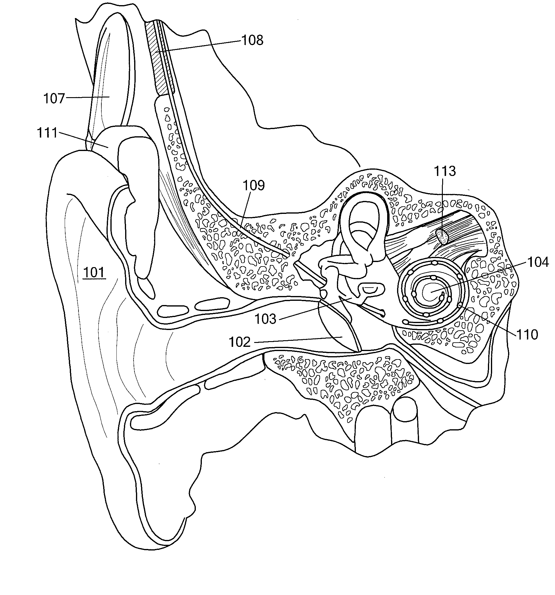
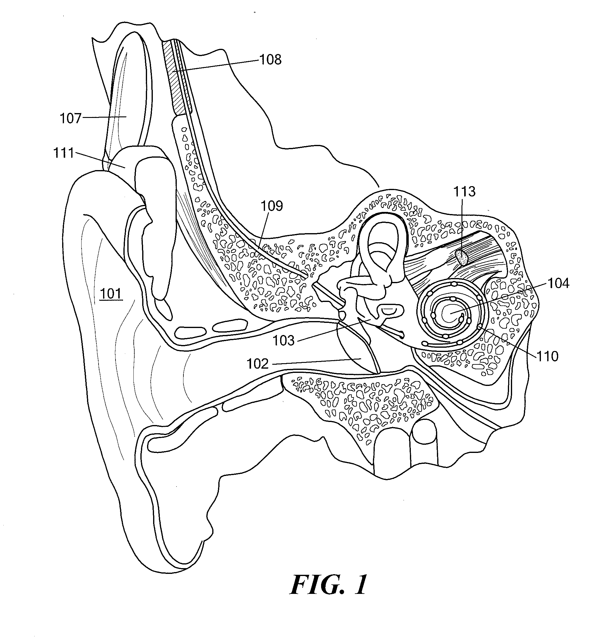
[0001]This application claims priority from U.S. Provisional Patent Application 61 / 360,123, filed Jun. 30, 2010, incorporated herein by reference.FIELD OF THE INVENTION[0002]The present invention relates to cochlear implants, and specifically to the signal processing used therein.BACKGROUND ART[0003]A normal ear transmits sounds as shown in FIG. 1 through the outer ear 101 to the tympanic membrane (eardrum) 102, which moves the bones of the middle ear 103 (malleus, incus, and stapes) that vibrate the oval window and round window openings of the cochlea 104. The cochlea 104 is a long narrow duct wound spirally about its axis for approximately two and a half turns. It includes an upper channel known as the scala vestibuli and a lower channel known as the scala tympani, which are connected by the cochlear duct. The cochlea 104 forms an upright spiraling cone with a center called the modiolar where the spiral ganglion cells of the acoustic nerve 113 reside. In response to received sound...

Claims


Application Information

Patent Timeline
IPC IPC(8): A61F11/04A61N1/372
CPCA61N1/36032A61N1/36038A61N1/36034H04R25/606
Inventor MEISTER, DIRKFRUHAUF, FLORIAN
Owner MED EL ELEKTROMEDIZINISCHE GERAETE GMBH
Learn More