Ear Implant Electrode and Method of Manufacture

a technology of implant electrodes and electrodes, applied in the field of implant electrode arrays, can solve the problems of poor welding of contacts, large amount of hand assembly of present-day ci electrode arrays, and need of electrode insertion tools, and achieve the effect of controlling bending flexibility and bending flexibility

Active Publication Date: 2012-01-05
MED EL ELEKTROMEDIZINISCHE GERAETE GMBH
View PDF5 Cites 43 Cited by
  • Summary
  • Abstract
  • Description
  • Claims
  • Application Information

AI Technical Summary

Benefits of technology

[0019]Embodiments of the present invention are directed to an electrode array for ear implant systems such as cochlear implants (CI) and vestibular implants (VI). At a terminal end of each electrode wire is an electrode stimulation contact for applying the electrical stimulation signals to adjacent neural tissue. An electrode carrier of resilient material encases the electrode wires and has an outer surface with a plurality of contact openings exposing the stimulation contacts. Multiple bend control elements are distributed along the length of the electrode array to control bending flexibility of the electrode array as a function of a bend radius threshold. The bend control elements may be made of a softer material than the electrode carrier material. The bending flexibility may be controlled to be greater for bending less than the bend radius threshold and lesser for bending greater than the bend radius threshold. The bending flexibility may be anisotropic to be greater in one direction than another.

Problems solved by technology

Some electrode array designs are pre-curved, though a drawback of that approach is that a special electrode insertion tool is needed which keeps the electrode array straight until the point of insertion.
Present day CI electrode arrays require considerable amount of hand assembly during manufacturing.
Some rejects inevitably occur during manufacturing due to open or short circuits between wires, or poor welding to the contacts.
Silicone overflow on contact surfaces may cause further rejects.
The process of making electrodes is extremely labor intensive and a considerable percentage of rejected electrodes is unavoidable since maintenance of acceptable quality is difficult.
In addition, the manual work is very operator dependent and difficult to specify in adequate detail to give reproducible results.
Hand-made devices may therefore unintentionally and undesirably be subject to significant variations in performance.
Furthermore, manual work is linked with extensive and time-consuming training of personnel and manual production may in general not be financially competitive.
The requirements as to number of stimulation channels, size, and mechanical properties constitute a challenging problem for traditional and modern electrode manufacturing techniques.
As explained earlier, these characteristics are generally not desirable in CIs since they should be highly bendable in all directions to lower the risk of implantation trauma.
It is therefore a challenge to produce CI electrodes that make use of the highly flexible helical shaped wires.

Method used


Image

  • Ear Implant Electrode and Method of Manufacture
  • Ear Implant Electrode and Method of Manufacture
  • Ear Implant Electrode and Method of Manufacture

Examples


Embodiment Construction

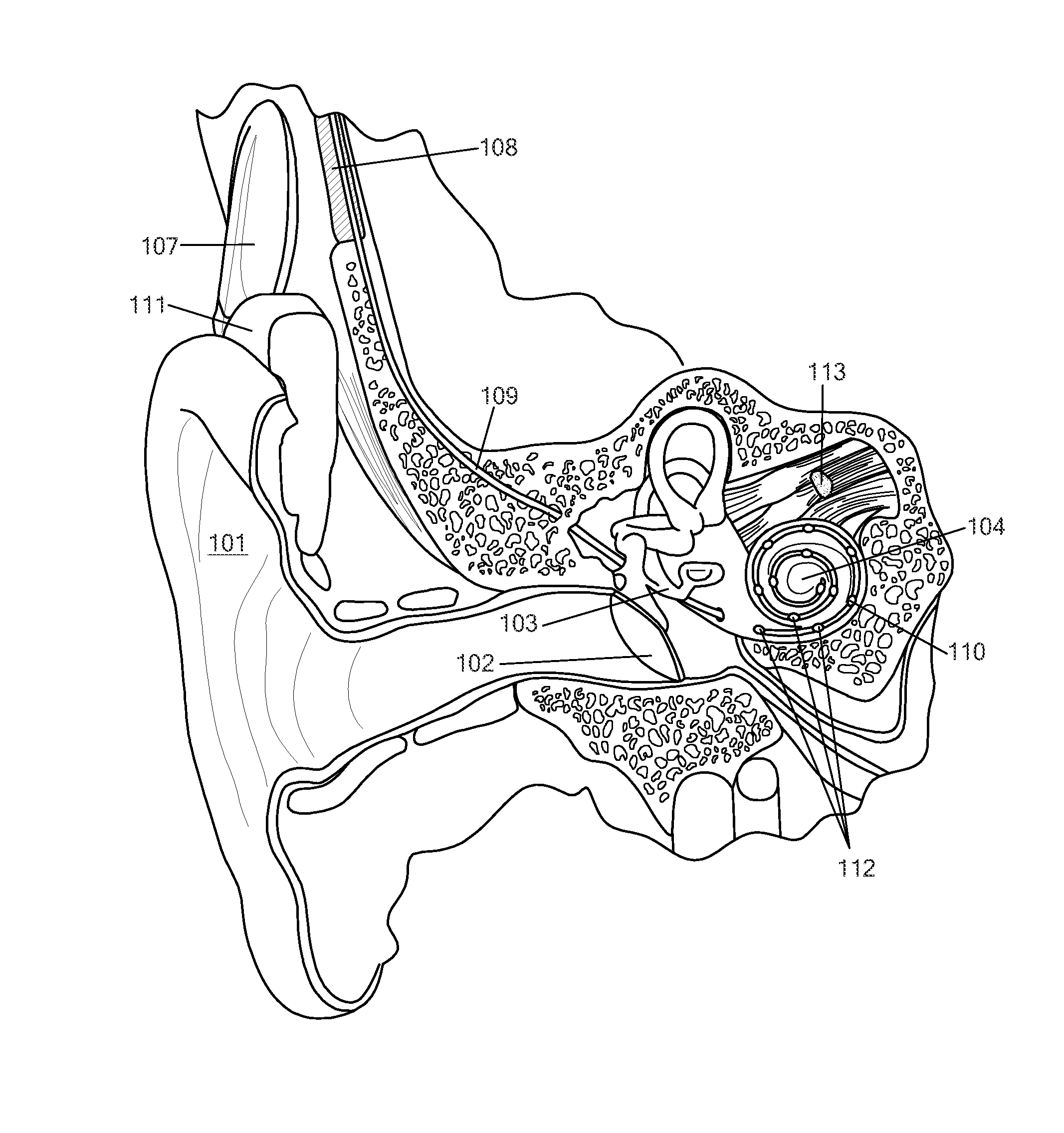
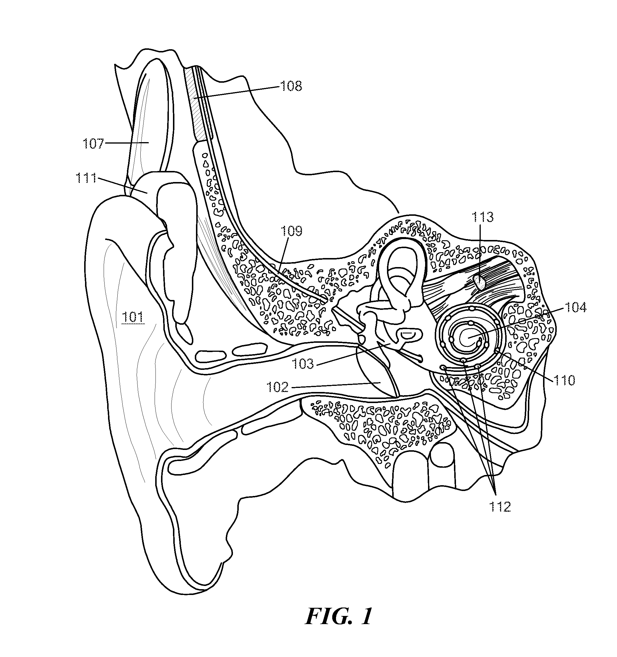
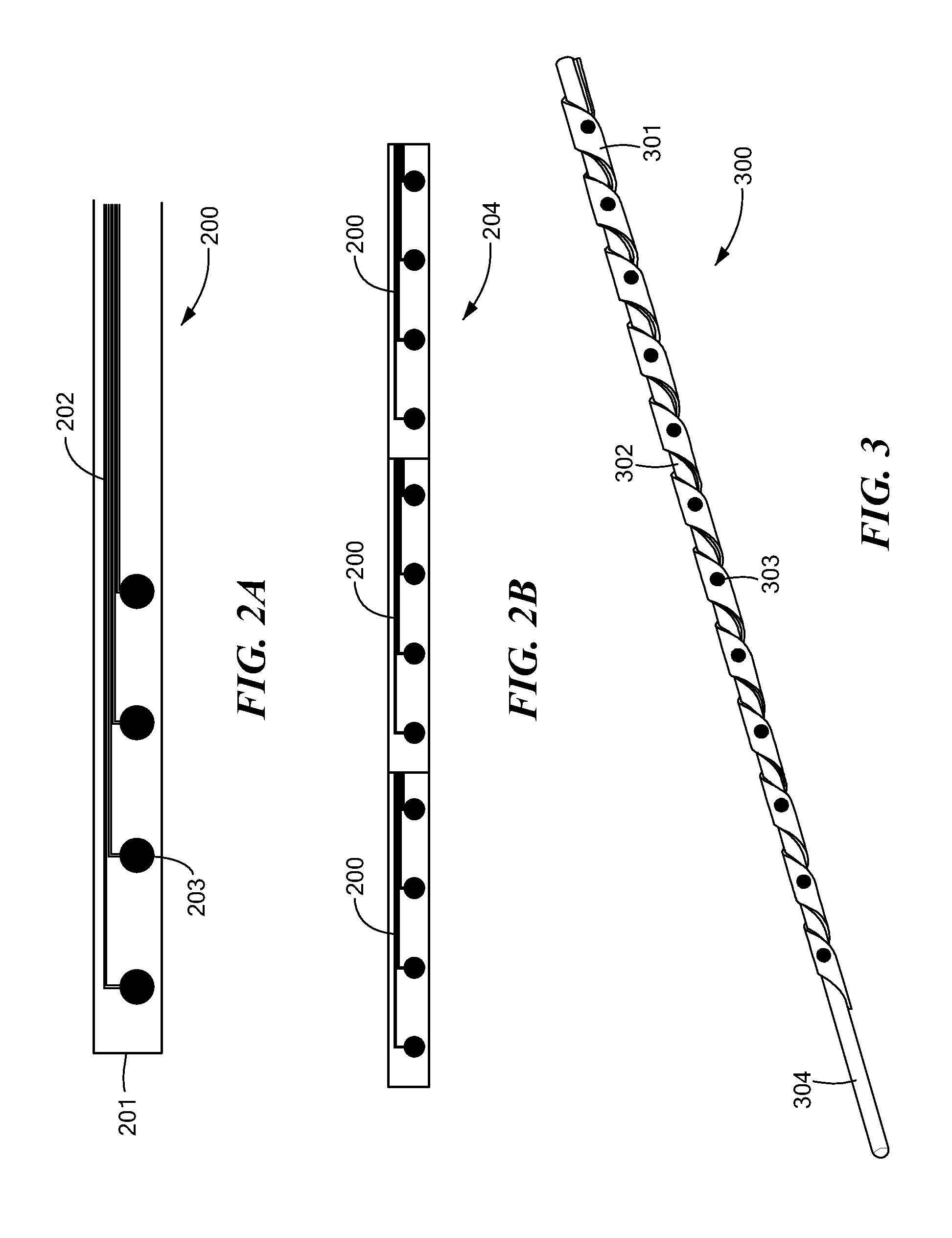
[0045]Embodiments of the present invention are directed to an ear implant electrode array. Bend control elements are distributed along the length of the electrode array to control bending flexibility of the electrode array as a function of a bend radius threshold. For a bending radius below the threshold which an electrode array normally can reach within the cochlea due to cochlear anatomy, the flexibility of the electrode array is maximum (i.e. minimum spring-back force when bent), But for a bending radius below the threshold, (less than the smallest radius of the outer wall inside the scala tympani), the electrode array has an increased spring-back force. The highly flexible behavior for bending radiuses above the threshold allows electrode array insertion with reduced insertion forces and insertion trauma on the lateral wall of the cochlea. The increased spring-back behavior for bending radiuses below the threshold allows electrode array insertion without kinking or buckling.

[004...


PUM


Abstract

A novel electrode array is described for ear implant systems such as cochlear implants (CI) and vestibular implants (VI). The electrode array includes electrode wires for carrying electrical stimulation signals. At a terminal end of each electrode wire is an electrode stimulation contact for applying the electrical stimulation signals to adjacent neural tissue. An electrode carrier of resilient material encases the electrode wires and has an outer surface with a plurality of contact openings exposing the stimulation contacts. Multiple bend control elements are distributed along the length of the electrode array to control bending flexibility of the electrode array as a function of a bend radius threshold.

Description

[0001]This application claims priority from U.S. Provisional Patent Application 61 / 359,928, filed Jun. 30, 2010, which is incorporated herein by reference.FIELD OF THE INVENTION[0002]The present invention relates to medical implants, and more specifically to an implant electrode array used in ear implant systems such as cochlear implants (CI) and vestibular implants (VI).BACKGROUND ART[0003]A normal ear transmits sounds as shown in FIG. 1 through the outer ear 101 to the tympanic membrane (eardrum) 102, which moves the bones of the middle ear 103 (malleus, incus, and stapes) that vibrate the oval window and round window openings of the cochlea 104. The cochlea 104 is a long narrow duct wound spirally about its axis for approximately two and a half turns. It includes an upper channel known as the scala vestibuli and a lower channel known as the scala tympani, which are connected by the cochlear duct. The cochlea 104 forms an upright spiraling cone with a center called the modiolar wh...

Claims


Application Information

Patent Timeline
Patent Type & Authority Applications(United States)
IPC IPC(8): A61F11/04A61N1/05
CPCA61N1/0541
Inventor RAMACHANDRAN, ANUPNIELSEN, STEFAN B.JOLLY, CLAUDEZIMMERLING, MARTIN
Owner MED EL ELEKTROMEDIZINISCHE GERAETE GMBH
Why Eureka
Try Eureka