Carbon nanotube hybrid photovoltaics

a hybrid photovoltaic and carbon nanotube technology, applied in nanosensors, nanoinformatics, solid-state devices, etc., can solve the problems of heterojunction photovoltaic systems that have so far demonstrated poor performan

Active Publication Date: 2012-01-12
RGT UNIV OF MICHIGAN
View PDF30 Cites 11 Cited by
  • Summary
  • Abstract
  • Description
  • Claims
  • Application Information

AI Technical Summary

Problems solved by technology

However, contrary to expectation similarly constructed bulk heterojunction photovoltaic systems have thus far demonstrated poor performance.

Method used


Image

  • Carbon nanotube hybrid photovoltaics
  • Carbon nanotube hybrid photovoltaics
  • Carbon nanotube hybrid photovoltaics

Examples


Embodiment Construction

[0035]The following description contains illustrations of devices, systems and methods according to the invention for purposes of promoting an understanding of such embodiments the invention, among other things. It should be understood that the scope of the invention is not limited by these embodiments. Alterations and modifications of the features of the invention, as well as additional applications of its principles in other forms or embodiments, such as those which would normally occur to one skilled in the relevant art having possession of this disclosure, are to be considered within the scope of the invention as claimed.

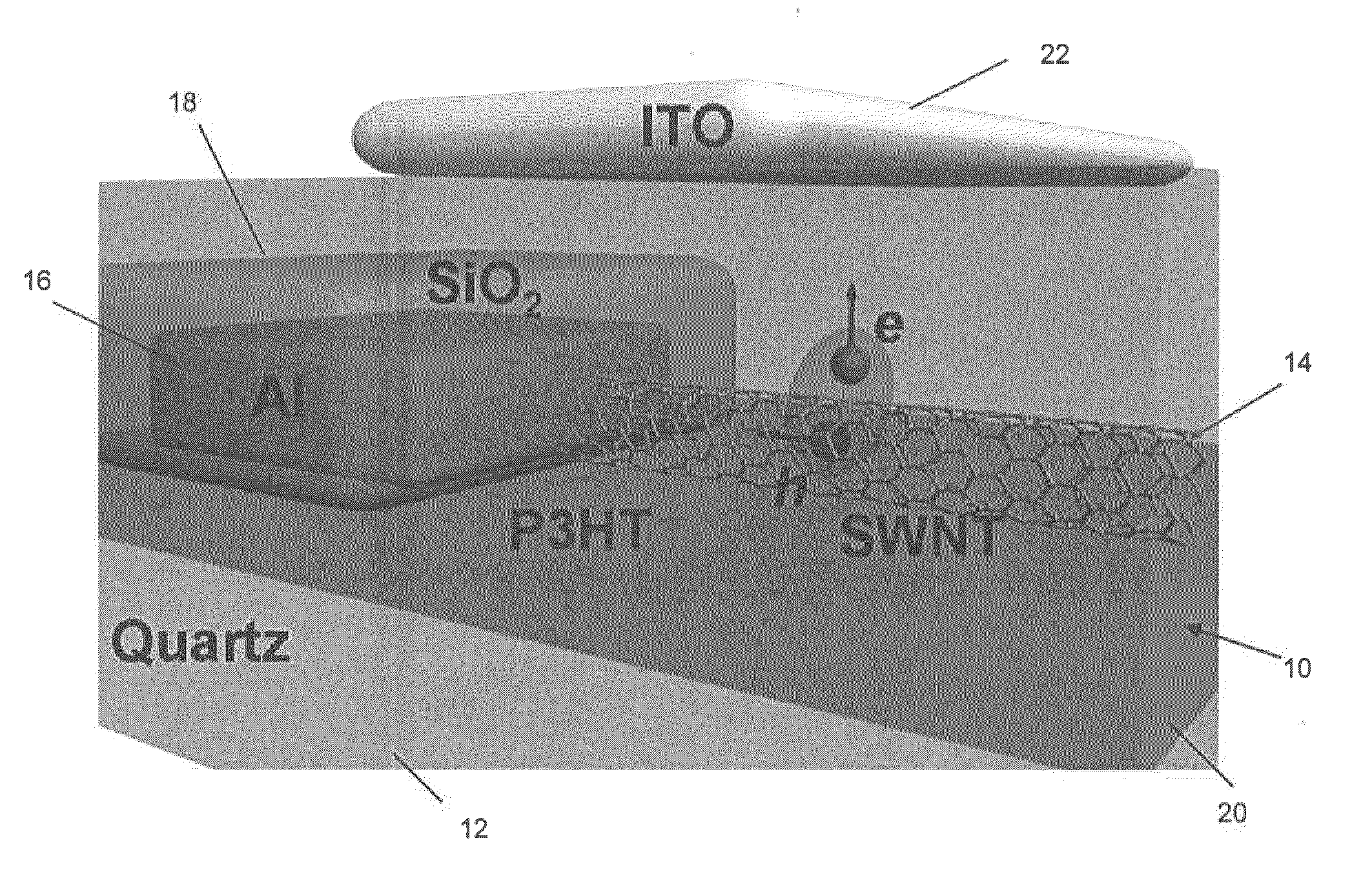
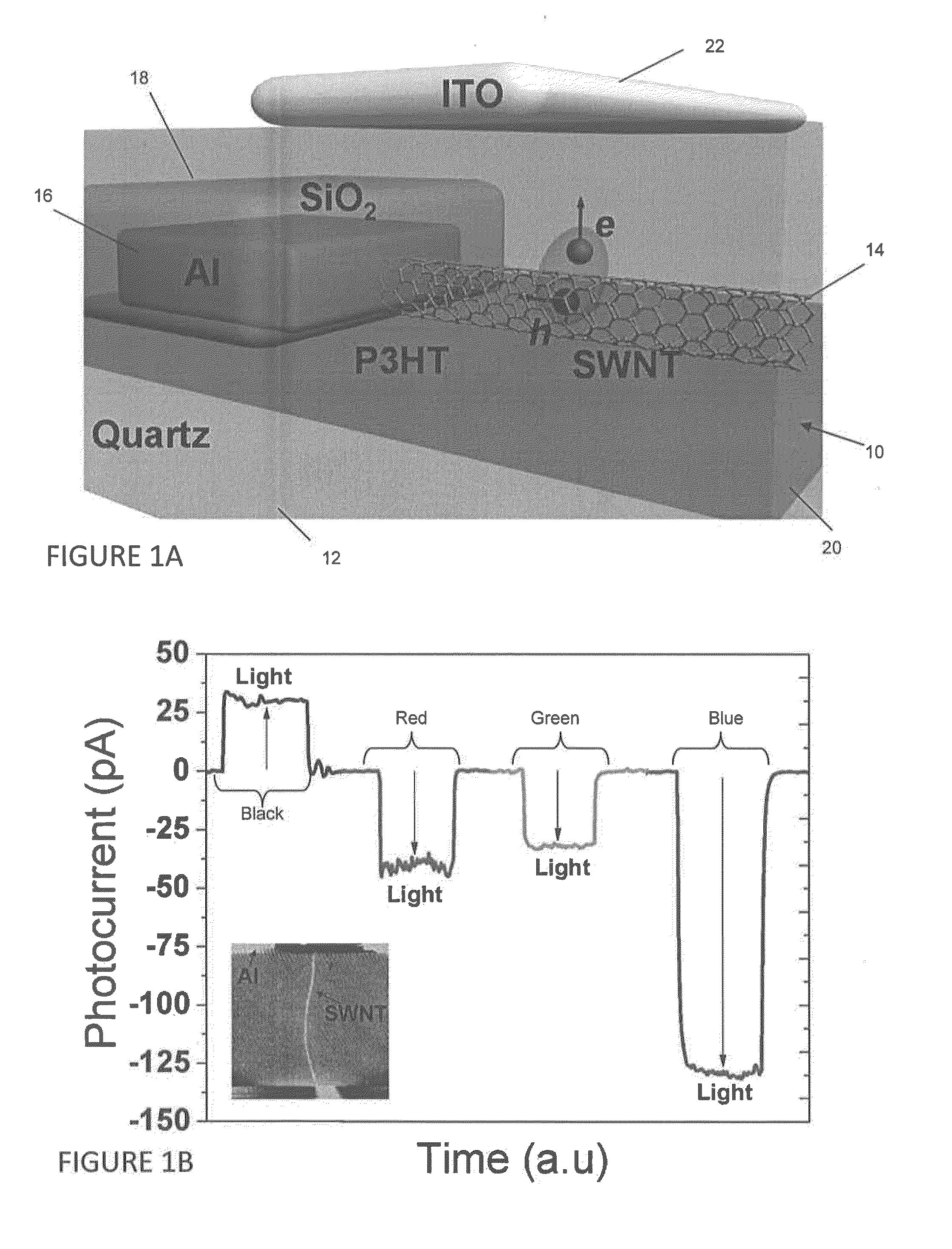
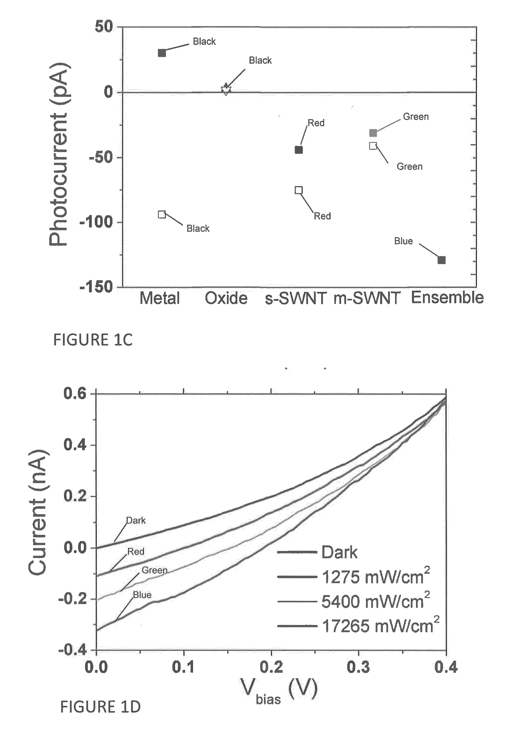
[0036]FIG. 1A illustrates an exemplary embodiment of a device constructed according to the invention which is generally referred to by the reference number 10. In this embodiment, device 10 includes a single junction SWNT / P3HT bilayer photovoltaic formed on an insulating substrate 12, which may be quartz or another material that preferably facilitates the reduct...


PUM

PropertyMeasurementUnit
external quantum efficiencyaaaaaaaaaa
diameteraaaaaaaaaa
channel lengthaaaaaaaaaa

Abstract

Systems, methods and devices for the efficient photocurrent generation in single- or multi-walled carbon nanotubes, which includes (SWNTs) / poly [3-hexylthiophene-2,5-diyl] (P3HT) hybrid photovoltaics, and exhibit the following features: photocurrent measurement at individual SWNT / P3HT heterojunctions indicate that both semiconducting (s-) and metallic (m-) SWNTs function as excellent hole acceptors; electrical transport and gate voltage dependent photocurrent indicate that P3HT p-dopes both s-SWNT and m-SWNT, and exciton dissociation is driven by a built-in voltage at the heterojunction. Some embodiments include a mm2 scale SWNT / P3HT bilayer hybrid photovoltaics using horizontally aligned SWNT arrays, which exhibit greater than 90% effective external quantum efficiency, among other things, which advantageously provide carbon nanomaterial based low cost and high efficiency hybrid photovoltaics.

Description

CROSS REFERENCE TO RELATED APPLICATIONS[0001]This application claims priority to U.S. Provisional Patent Application Ser. No. 61 / 363,103, filed Jul. 9, 2010, the disclosure which is incorporated herein by reference.BACKGROUND OF THE INVENTION[0002]The present disclosure relates to systems and methods of efficient photocurrent generation and through hole transfer at individual metallic and semiconducting single-walled carbon nanotube / poly [3-hexylthiophene-2,5-diyl] junctions, among other things.[0003]The following description of the background of the invention is provided to aid in understanding the invention, but is not admitted to describe or constitute prior art to the invention. The contents of the articles, patents, and patent applications, and all other documents and electronically available information mentioned or cited in this application, are hereby incorporated by reference in their entirety to the same extent as if each individual publication was specifically and individ...

Claims


Application Information

Patent Timeline
Patent Type & Authority Applications(United States)
IPC IPC(8): H01L51/44H01L51/48B82Y15/00B82Y40/00
CPCB82Y10/00B82Y30/00Y02E10/549H01L51/0048H01L51/4253H01L51/0036H10K85/221H10K85/113H10K30/30H10K30/50
Inventor DISSANAYAKE, NANDITHAZHONG, ZHAOHUI
Owner RGT UNIV OF MICHIGAN
Why Eureka
Try Eureka