Electrical machine

a technology of electric machines and electric motors, applied in the field of electric machines, can solve the problems of reducing reducing the rotational torque and power, and limiting the use of isotropic materials, and achieve the effect of preventing the flux

Active Publication Date: 2012-01-12
E V R MOTORS
View PDF9 Cites 24 Cited by
  • Summary
  • Abstract
  • Description
  • Claims
  • Application Information

AI Technical Summary

Benefits of technology

[0025]A further object of the invention is to disclose the permanent magnets provided with extension members magnetically connected thereto; the extension members are adapted for shunting a magnetic flux generated by the electromagnets. The extension member

Problems solved by technology

Use of isotropic material is limited by technical problems with producing magnetic conductors of large dimension and complex configuration which link sources of magnetic field in the electric machine.
A second group of losses is attributed to the electrical machine with permanent magnets.
The afore

Method used


Image

  • Electrical machine
  • Electrical machine
  • Electrical machine

Examples


Embodiment Construction

[0121]The following description is provided, alongside all chapters of the present invention, so as to enable any person skilled in the art to make use of said invention and sets forth the best modes contemplated by the inventor of carrying out this invention. Various modifications, however, are adapted to remain apparent to those skilled in the art, since the generic principles of the present invention have been defined specifically to provide electrical machines provided-with-magnetic conductors made of magnetically isotropic and anisotropic material to reduce losses in the aforesaid conductors.

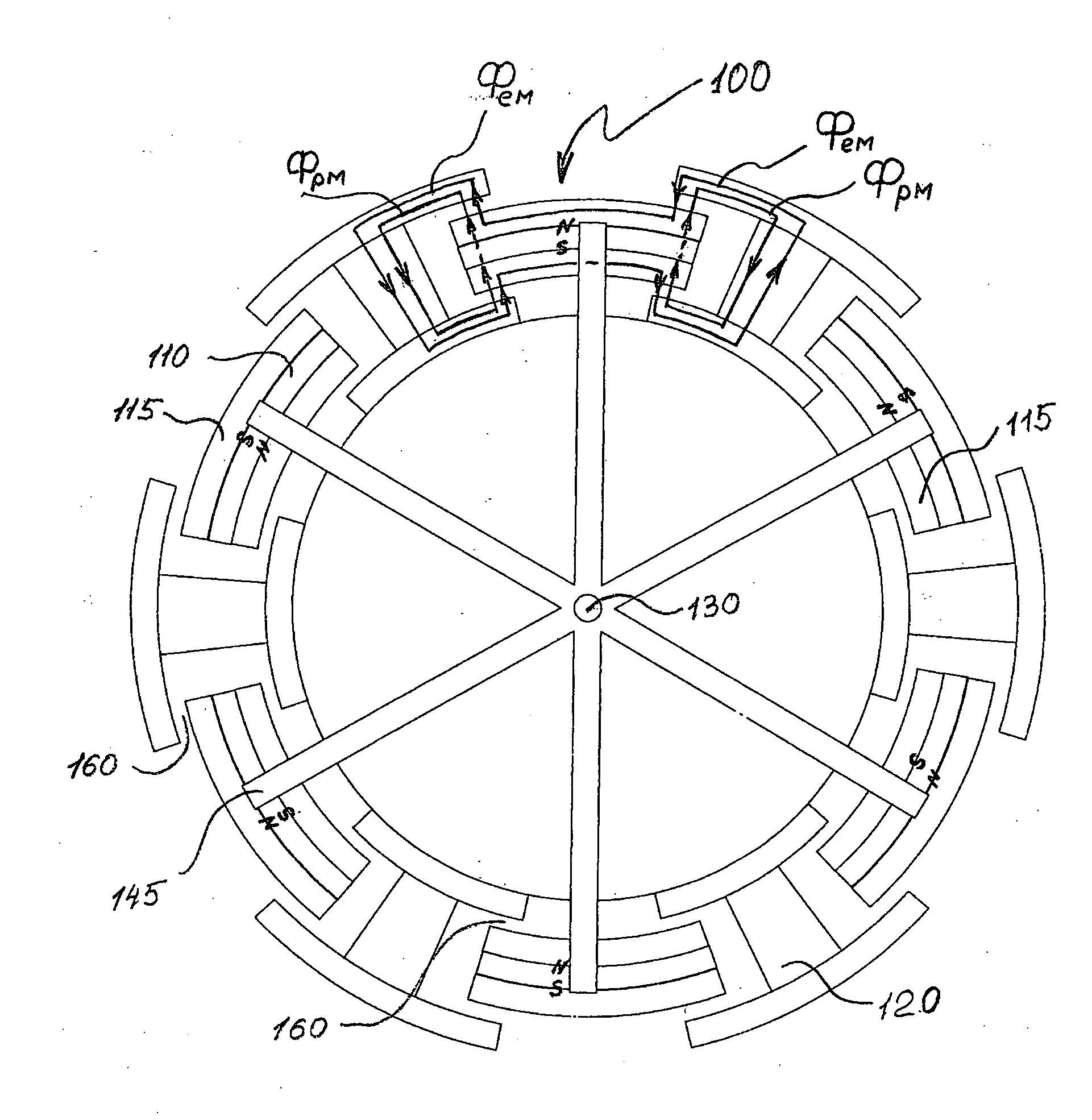
[0122]The term “polar pitch τ” hereinafter refers to a portion of an electrical machine armature (rotor or stator) which falling on one pole. Specifically, τ=D / 2p, where D is an armature diameter and 2p is a number of main poles in the electrical machine. The diameter D is measured in an area of the air gap in degrees.

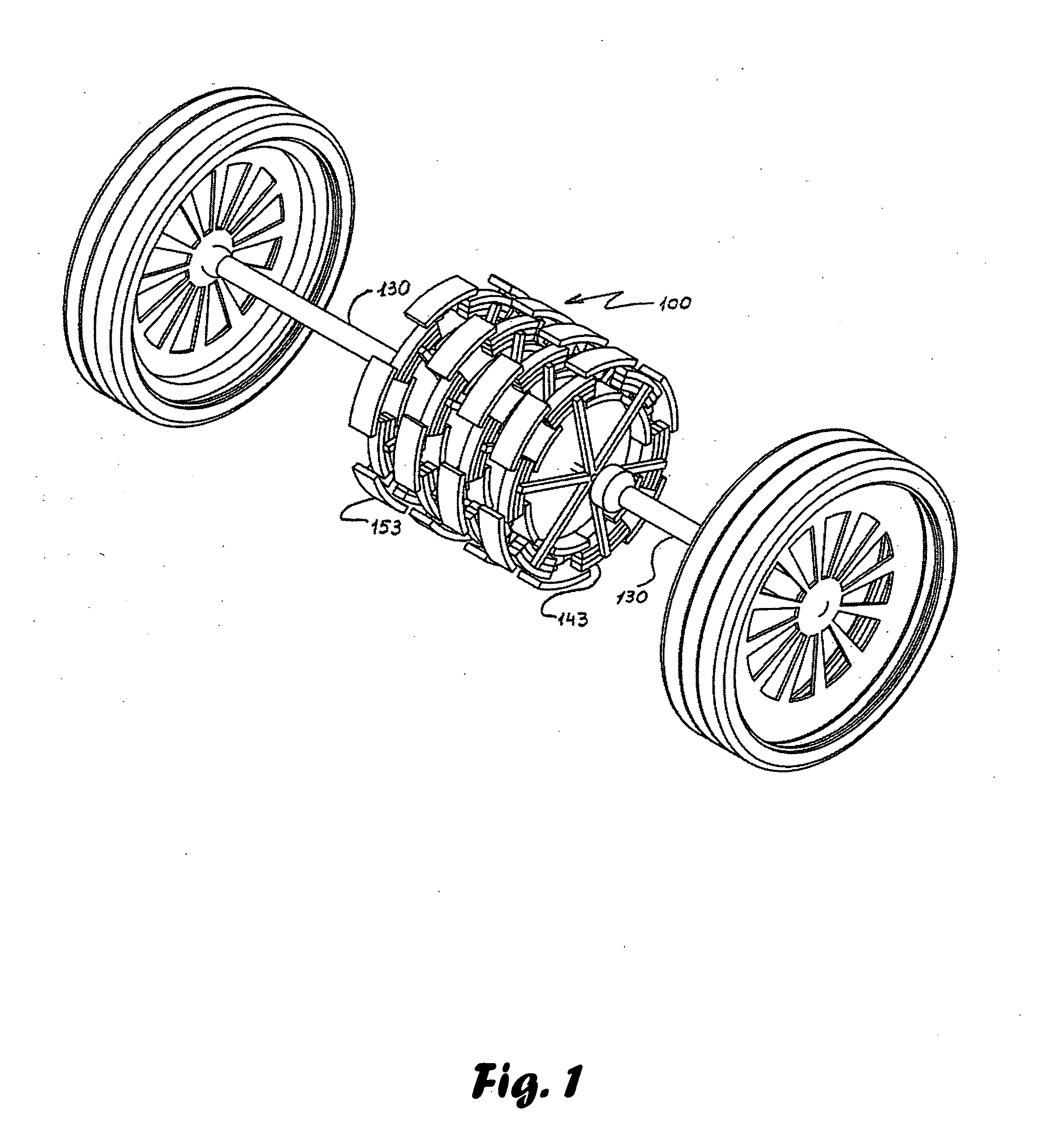
[0123]Reference is now made to FIG. 1, presenting an electrical machine 1...


PUM


Abstract

An electrical machine comprising a stator and a rotor rotatable relative to the stator with an air gap therebetween is disclosed. The stator is provided with a first plurality of sources of magnetic field which is equally spaced in a circumferential configuration over the stator. The rotor is provided with a second plurality of sources of magnetic field which is equally spaced in a circumferential configuration over the rotor. The magnetic sources of at least one plurality are electromagnets; each electromagnet comprises at least one magnet coil resting on a magnet conductor. The magnetic conductor comprises at least one member made of magnetically isotropic and/or anisotropic materials.

Description

FIELD OF THE INVENTION[0001]The present invention relates to electrical machines with electromagnetic excitation and / or with excitation by permanent magnets, and, more specifically, to electrical machines provided with magnetic conductors made of magnetically isotropic and anisotropic materials and their combination to reduce losses in the aforesaid circuits.BACKGROUND OF THE INVENTION[0002]Magnetic conductors of electric machines provide low magnetic reluctance when magnetic fluxes pass therethough. The magnetic fluxes are created by sources of magnetic field, specifically, an electromagnet coil and a permanent magnet. When the magnetic flux is conduct through the magnetic conductors, occurring losses define efficiency of an electrical machine.[0003]A first group of losses is determined by and a configuration of magnetic conductor and a material from which the aforesaid magnetic conductor is made. These loses are heat generation when a slowly varying is conducted by the magnetic co...

Claims


Application Information

Patent Timeline
IPC IPC(8): H02K21/12H02K1/02
CPCH02K1/02H02K21/38H02K1/06H02K1/14H02K1/141H02K1/17H02K1/18H02K1/27H02K16/00H02K16/02H02K19/10H02K21/12H02K21/24H02K21/26H02K21/28H02K1/04B60L15/20B60L15/2036B60L15/2045B60L2220/52B60L2240/423B60L2260/26B60L2270/145Y02T10/64Y02T10/72
Inventor ROZINSKY, ELIYAHUKISLEV, VIKTORSHABINSKI, RUSLAN
Owner E V R MOTORS
Why Eureka
Try Eureka