

Resonator antenna
a technology of resonator antennas and antenna elements, applied in the direction of antennas, antenna details, electrically short antennas, etc., can solve the problem of difficult miniaturization and achieve the effect of suppressing the area and minimizing the antenna elemen
- Summary
- Abstract
- Description
- Claims
- Application Information
AI Technical Summary
Benefits of technology
Problems solved by technology
Method used
Image

Examples
second embodiment
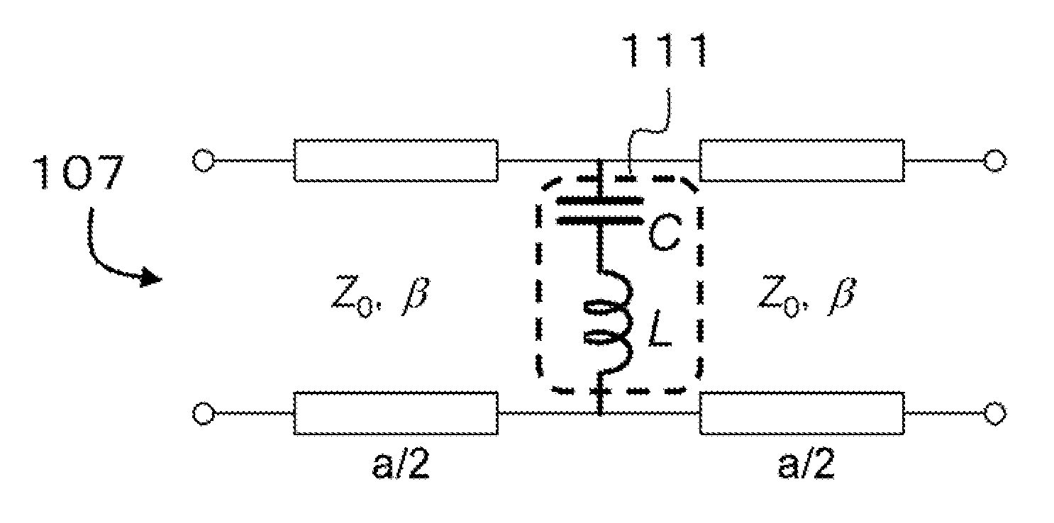
[0073]In order to achieve further miniaturization of the resonator, a plane-type inductance element 109 can also be introduced. Because of the presence of the plane-type inductance element 109, the meta-material 210 used in a resonator antenna 201 according to a second embodiment of the invention more drastically increases in the inductance L in the equivalent circuit per unit cell shown in FIG. 5 and more decreases in the series resonance frequency of the serial resonance circuit 111 than the meta-material 110 used in the resonator antenna 101 according to the first embodiment of the invention. As a result, since the stop band is shifted to the low-frequency side, the phase velocity in the passband appearing at the lowest-frequency side is reduced, and the resonator can be miniaturized.
[0074]FIG. 11 shows a cross-sectional view illustrating the resonator antenna 201 according to the second embodiment of the invention. In comparison with the cross-sectional view of the resonator ant...
third embodiment
[0084]It is also possible to provide the plane-type inductance element in the conductor layer distinct from the conductor plane. FIG. 14 shows a cross-sectional view illustrating a resonator antenna 301 according to a third embodiment of the invention. A meta-material 310 used in the resonator antenna 301 according to the third embodiment of the invention is constituted by four conductor layers. With this, the resonator antenna 301 according to the third embodiment is also constituted by a total of four conductor layers of a layer provided with the conductor element 102 which is an antenna element, a layer in which the periodic array of the conductor strips 104 is formed, a layer of the conductor plane 103 periodically provided with the openings 108, and a layer in which the plane-type inductance element 109 is formed.
[0085]The first dielectric layer 114 is interposed between the layer provided with the conductor element 102 and the layer in which the periodic array of the conductor...
fourth embodiment
[0094]In the resonator antenna according to the first to third embodiments of the invention, although a structure is formed in which the conductor element 102 which is an antenna element is not electrically connected to the conductor post 105, a structure may be formed in which the conductor element 102 is electrically connected to the conductor post 105 by turning the layer configuration of the resonator 112 upside down. At this time, the equivalent circuit per unit cell is completely equivalent to that shown in FIG. 5 only by turning the layer configuration of the meta-material within the resonator 112 upside down.
[0095]FIG. 16(a) shows a cross-sectional view illustrating a resonator antenna 401a according to a fourth embodiment of the invention in which the meta-material 110 constituting the resonator antenna 101 according to the first embodiment of the invention is used. In the resonator antenna 401a according to the fourth embodiment of the invention, the conductor strip 104 co...
PUM
 Abstract
Description
Claims
Application Information