Capacitive touch panel

a touch panel and capacitive technology, applied in the field of capacitive touch panels, can solve the problems of further limiting the application range, damage, and easy collision of the touch sensitive layer b>62/b>, and achieve the effect of high production yield and suitable manufacturing

Active Publication Date: 2012-01-12
TPK HLDG
View PDF4 Cites 76 Cited by
  • Summary
  • Abstract
  • Description
  • Claims
  • Application Information

AI Technical Summary

Benefits of technology

[0007]An objective of the present invention is to provide a capacitive touch panel having a re

Problems solved by technology

Because of the low yield, such capacitive touch panels do not aim for large-size touch panel, thereby further limiting the application

Method used


Image

  • Capacitive touch panel
  • Capacitive touch panel
  • Capacitive touch panel

Examples


Embodiment Construction

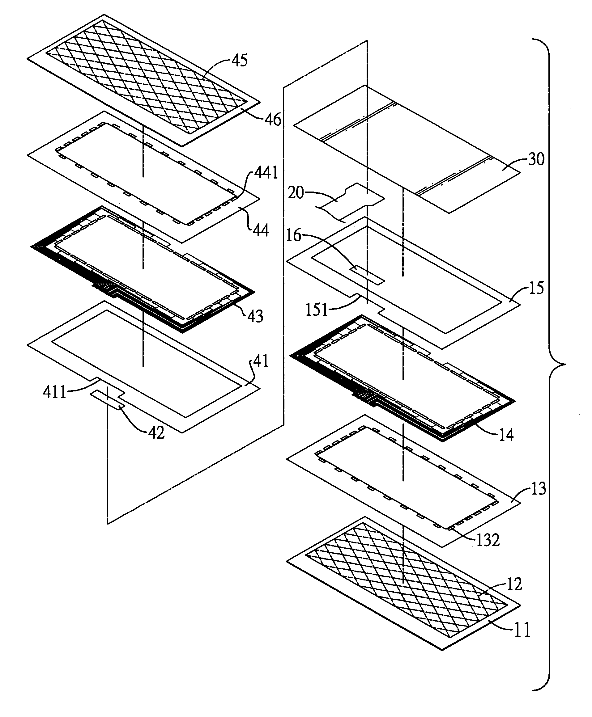
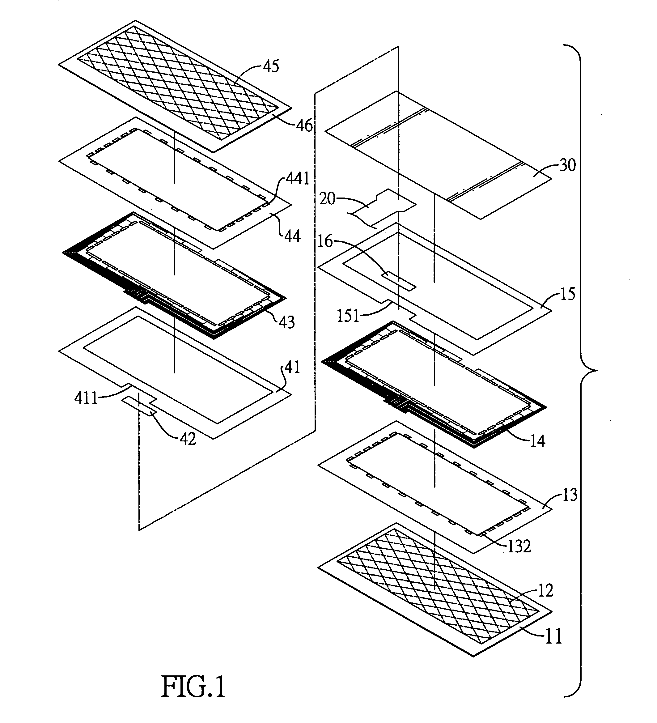
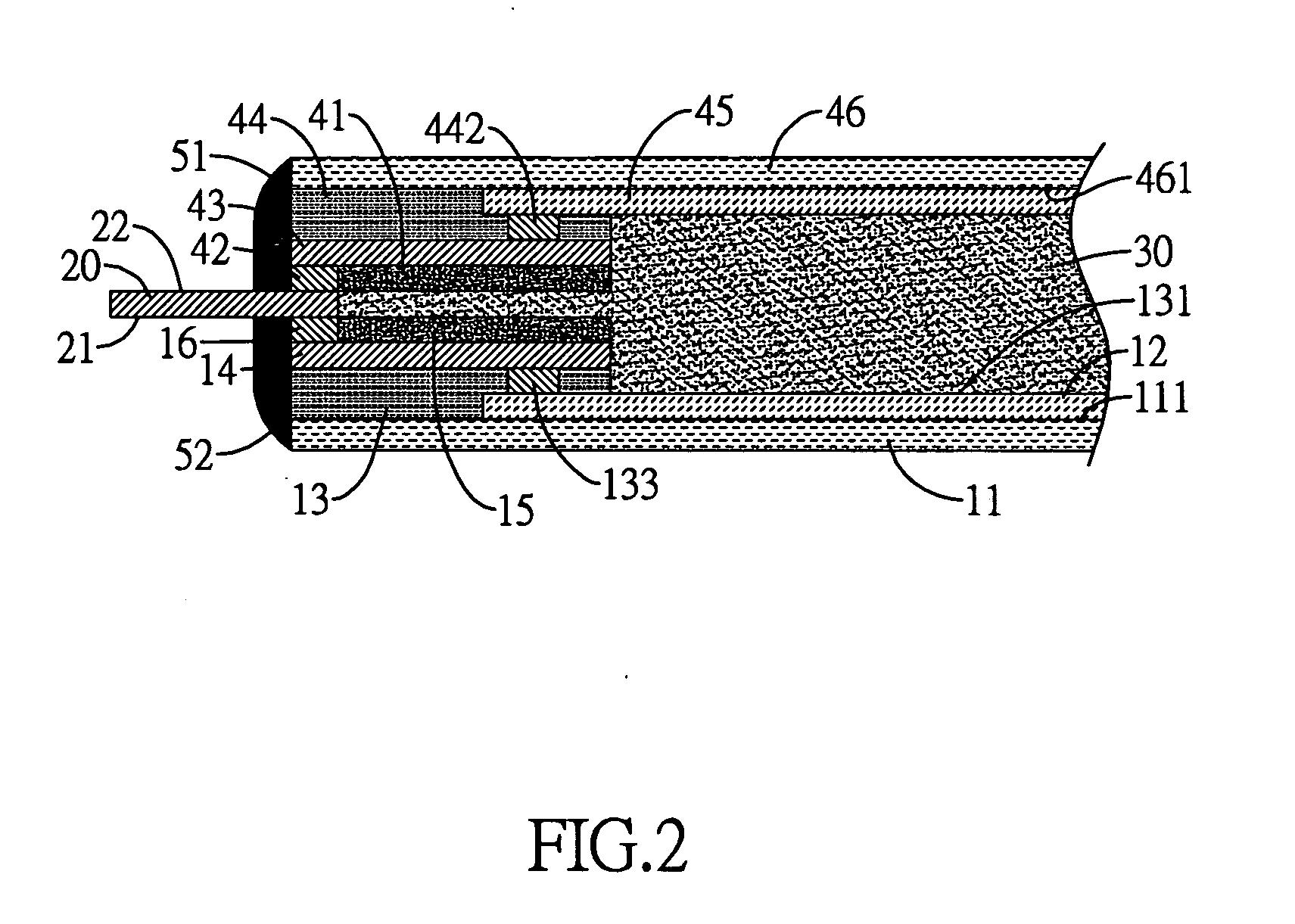
[0028]With reference to FIGS. 1 and 2, a capactive touch panel has a first glass substrate 11, a lower touch sensitive layer 12, a lower insulation ink layer 13, a lower conductor layer 14, a lower insulation layer 15, a lower conductive adhesive layer 16, a flexible circuit board 20, a transparent insulation adhesive layer 30, an upper insulation layer 41, an upper conductive adhesive layer 42, an upper conductor layer 43, an upper insulation ink layer 44, an upper touch sensitive layer 45, a second glass substrate 46, an upper protection layer 51 and a lower protection layer 52.

[0029]The first glass substrate 11 has a first circuit surface 111.

[0030]The lower touch sensitive layer 12 is mounted on the first circuit surface 111 of the first glass substrate 11. In the present embodiment, the lower touch sensitive layer 12 has a lower touch circuit of a double-layer touch electrode layer, such as an X-axis touch circuit.

[0031]The lower insulation ink layer 13 is mounted on an edge po...


PUM


Abstract

A capacitive touch panel sequentially has a first glass substrate, a lower touch sensitive layer, a lower insulation ink layer, a lower conductor layer, a lower insulation layer, a lower conductive adhesive layer, a flexible circuit board, a transparent insulation adhesive layer, an upper insulation layer, an upper conductive adhesive layer, an upper conductor layer, an upper insulation ink layer, an upper touch sensitive layer and a second glass substrate. The aforementioned structure allows fabrication of the capacitive touch panel to be separated into a lower panel fabrication process and an upper panel fabrication process. The two independent fabrication processes prevent the capacitive touch panel from being damaged in one of the processes when the process is completed so as to increase the yield in production and further facilitate producing large-size touch panel.

Description

BACKGROUND OF THE INVENTION[0001]1. Field of the Invention[0002]The present invention is related to a capacitive touch panel, and more particularly to a capacitive touch panel having a relatively high yield in production and being suitable for manufacture of large-size touch panel.[0003]2. Description of the Related Art[0004]Existing touch panels can be classified as resistive touch panels and capacitive touch panels. Recently, the capacitive touch panels become increasingly popular in the market.[0005]With reference to FIG. 3, a conventional touch panel has a first glass substrate 61, a lower touch sensitive layer 62, an upper touch sensitive layer 63, a flexible circuit board 64, a transparent insulation adhesive layer 65 and a second glass substrate 66. The first glass substrate 61 has a top surface and a bottom surface. The upper touch sensitive layer 63 and the lower touch sensitive layer 62 are respectively formed on the top surface and the bottom surface of the first glass su...

Claims


Application Information

Patent Timeline
IPC IPC(8): G06F3/045
CPCG06F2203/04103G06F3/044G06F3/0445H03K17/962
Inventor MI, DAVID
Owner TPK HLDG
Why Eureka
Try Eureka