Shadow Removal in an Image Captured by a Vehicle-Based Camera Using an Optimized Oriented Linear Axis

a vehicle-based camera and linear axis technology, applied in the field of can solve the problems of high-quality imagers, ambiguities between cameras, and errors in vision-based object detection systems, and achieve the effects of reducing shadows, optimizing a linear axis slope, and minimizing intra-variation among color values

Active Publication Date: 2012-01-12
GM GLOBAL TECH OPERATIONS LLC
View PDF1 Cites 26 Cited by
  • Summary
  • Abstract
  • Description
  • Claims
  • Application Information

AI Technical Summary

Benefits of technology

[0004]An advantage of an embodiment is the reduction of shadows from an image captured by an image capture device that is to be analyzed by a vehicle-based vision sensing system. The shadow-reduction technique optimizes a slope of a linear axis so that intra-variation among color values is minimized and inter-variation between color sets is maximized so that it distinguishes and preserves the color chromaticity of each color set while removing any lighting influence exerted on a respective color set.
[0005]An embodiment contemplates a method for removing an illumination generated shadow in a captured image. An input image of a scene is captured by an image capture device. Each pixel of the captured input image is plotted on a two dimensional logarithmic graph. Each pixel is a color variation of one of a plurality of color sets in the logarithmic graph. A linear axis for the plurality of color sets is determined. The linear axis is substantially orthogonal to a respective illumination direction of each respective color set. A log-chromaticity value of each plotted pixel is projected on the axis. Each plotted pixel on the linear axis represents a color value of the respective pixels of the input image mapped to an illumination-invariant image domain. An orientation of the linear axis is selected to minimize an illumination effect in the image and provide an optimum separation between each of the respective color sets projected on the linear axis. Edges in the input image are identified. Edges in the illumination invariant image domain are identified. The identified edges of the input image are compared to identified edges in the illumination invariant image domain. A determination is made whether a shadow edge is present in response to an edge identified in the input image and an absence of a correlating edge in the illumination invariant image domain. A shadow-reduced image is generated for scene analysis by a vehicle vision-based system.

Problems solved by technology

Illumination conditions such as shadows can cause errors in the vision-based object detection systems.
Shadows distort the color of a captured object resulting in ambiguities between (1) edges due to shadows and (2) edges between different entities (e.g., road and landscape).
Cameras with high quality imagers are expensive with large packaging sizes, and therefore, not practical especially in a mass-produced vehicle based vision system.
However, a low cost imager typically used in vehicle vision based object detection systems does not conform to the narrow-band sensor assumption.
Therefore, previous techniques for shadow removal are inapplicable with the use low cost production imagers.
Maximizing inter-variation between color sets is not a feasible result under this approach described, particularly, when numerous color sets are used.

Method used


Image

  • Shadow Removal in an Image Captured by a Vehicle-Based Camera Using an Optimized Oriented Linear Axis
  • Shadow Removal in an Image Captured by a Vehicle-Based Camera Using an Optimized Oriented Linear Axis
  • Shadow Removal in an Image Captured by a Vehicle-Based Camera Using an Optimized Oriented Linear Axis

Examples


Embodiment Construction

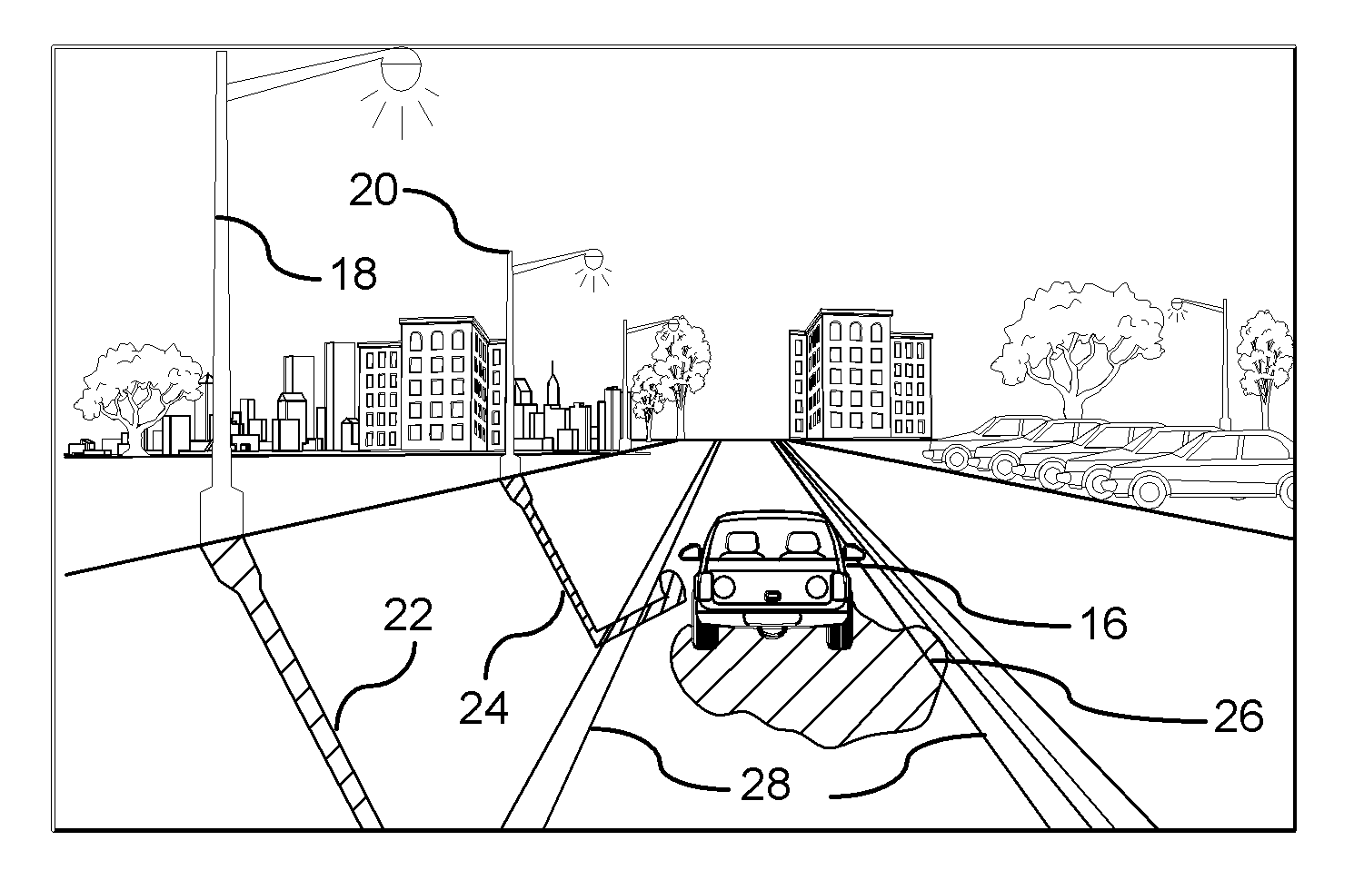
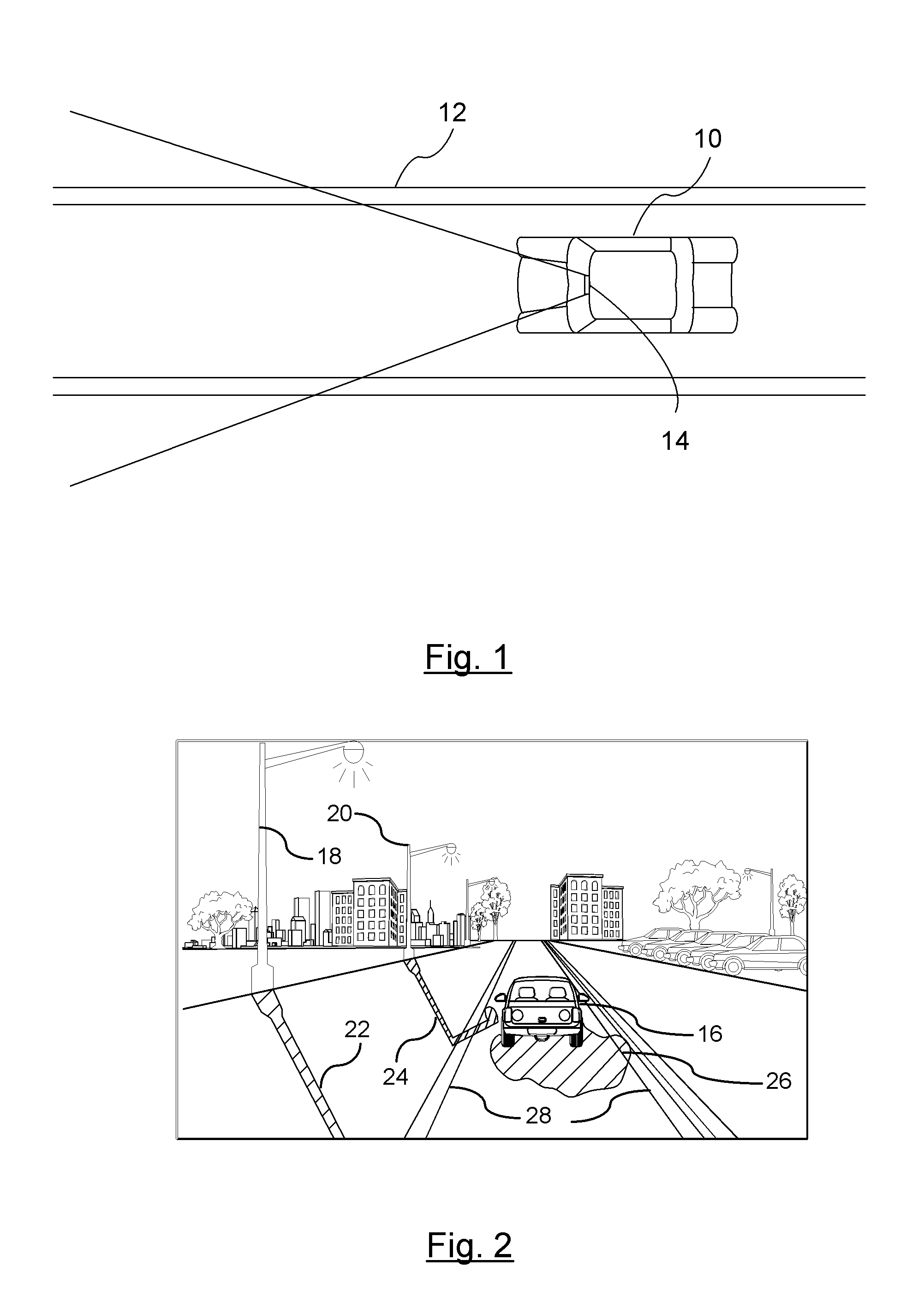
[0013]There is shown in FIG. 1, a vehicle 10 traveling along a road 12. A vision-based imaging device 14 captures images of the road forward of the vehicle 10 for detecting images in the feasible region of travel (hereinafter referred to as clear path). The vision-based imaging device 14 is used to detect objects. In a preferred embodiment, the vision-based imaging device 14 is used to identify the clear path or lane markings in the road for systems such as, but not limited to, lane departure warning systems. The vision-based imaging device 14 is preferably mounted in the interior of the vehicle just behind the windshield for capturing events occurring exterior and forward of the vehicle. Although the vision-based imaging device 14 may be used for a variety of functions (e.g., night vision enhancement for the driver), the primary purpose as described herein is for systems that require the recognition of road marking, lane markings, road signs, or other roadway objects. An example of...


PUM


Abstract

A method is provided for removing an illumination generated shadow in a captured image. Each pixel of the captured input image is plotted on a two dimensional logarithmic graph. A linear axis for the plurality of color sets is determined that is substantially orthogonal to a respective illumination direction of each respective color set. A log-chromaticity value of each plotted pixel is projected on the axis. An orientation of the linear axis is selected to minimize an illumination effect and provide optimum separation between each of the respective color sets on the linear axis. Edges in the input image and illumination invariant image domain are identified. The identified edges of the input image are compared to identify edges in the illumination invariant image domain. A determination is made whether a shadow edge is present in response to the comparison. A shadow-reduced image is generated for scene analysis by a vehicle vision-based system.

Description

BACKGROUND OF INVENTION[0001]An embodiment relates generally to vision-based object detection systems.[0002]Illumination conditions such as shadows can cause errors in the vision-based object detection systems. Shadows distort the color of a captured object resulting in ambiguities between (1) edges due to shadows and (2) edges between different entities (e.g., road and landscape). Applications have been used to filter out shadows but prior art systems assume the use of a camera having a high quality imager. Cameras with high quality imagers are expensive with large packaging sizes, and therefore, not practical especially in a mass-produced vehicle based vision system. With the use of high quality imager, the camera sensor is assumed to be narrow-banded and behave like Dirac delta functions in that they have a non-null response only at a single wavelength. However, a low cost imager typically used in vehicle vision based object detection systems does not conform to the narrow-band s...

Claims


Application Information

Patent Timeline
Patent Type & Authority Applications(United States)
IPC IPC(8): H04N9/64
CPCG06K9/00791G06K9/346G06T2207/30252G06T7/408G06T2207/10024G06T5/008G06T7/90G06V20/56G06V10/273
Inventor ZHANG, WENDEWU, QIBHAGAVATULA, VIJAYAKUMAR
Owner GM GLOBAL TECH OPERATIONS LLC
Why Eureka
Try Eureka