Liquid crystal display device

display device technology, applied in non-linear optics, instruments, optics, etc., can solve the problem of difficult to uniformly irradiate the entire surface of a liquid crystal display device by such a design, and achieve the effect of preventing non-uniform light irradiation more reliably

Inactive Publication Date: 2012-01-12
SHARP KK
View PDF2 Cites 9 Cited by
  • Summary
  • Abstract
  • Description
  • Claims
  • Application Information

AI Technical Summary

Benefits of technology

[0020]In a liquid crystal display device of such a configuration, by placing the anisotropic optical member of the plurality of optical memb

Problems solved by technology

Such a design disclosed in Patent Document 1 is, however, for expanding the light irradiation region from an individual point

Method used


Image

  • Liquid crystal display device
  • Liquid crystal display device
  • Liquid crystal display device

Examples


Embodiment Construction

[0038]Hereinafter, several preferred embodiments of the present invention are described with reference to the figures. The items which are not the matters specifically mentioned in this specification (optical members, for example), and are necessary to implement the present invention (such as a structure and a configuration method of a liquid crystal panel, and electric circuits related to a driving method of light sources installed in a liquid crystal display device, for example) can be understood as design matters of those skilled in the art based on the prior art in the field. The present invention can be implemented based on the contents disclosed in this specification and the technical common knowledge in the field.

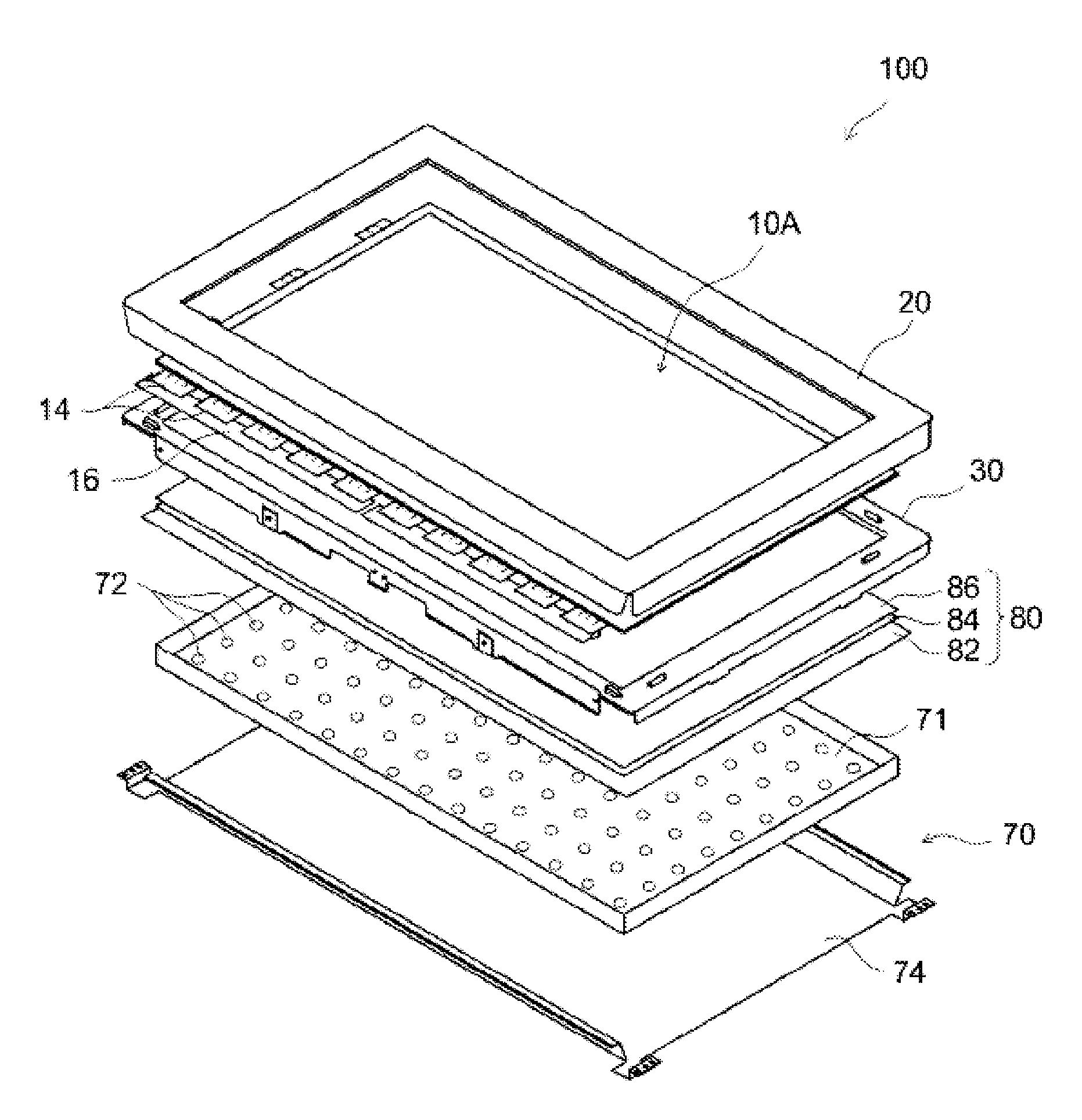
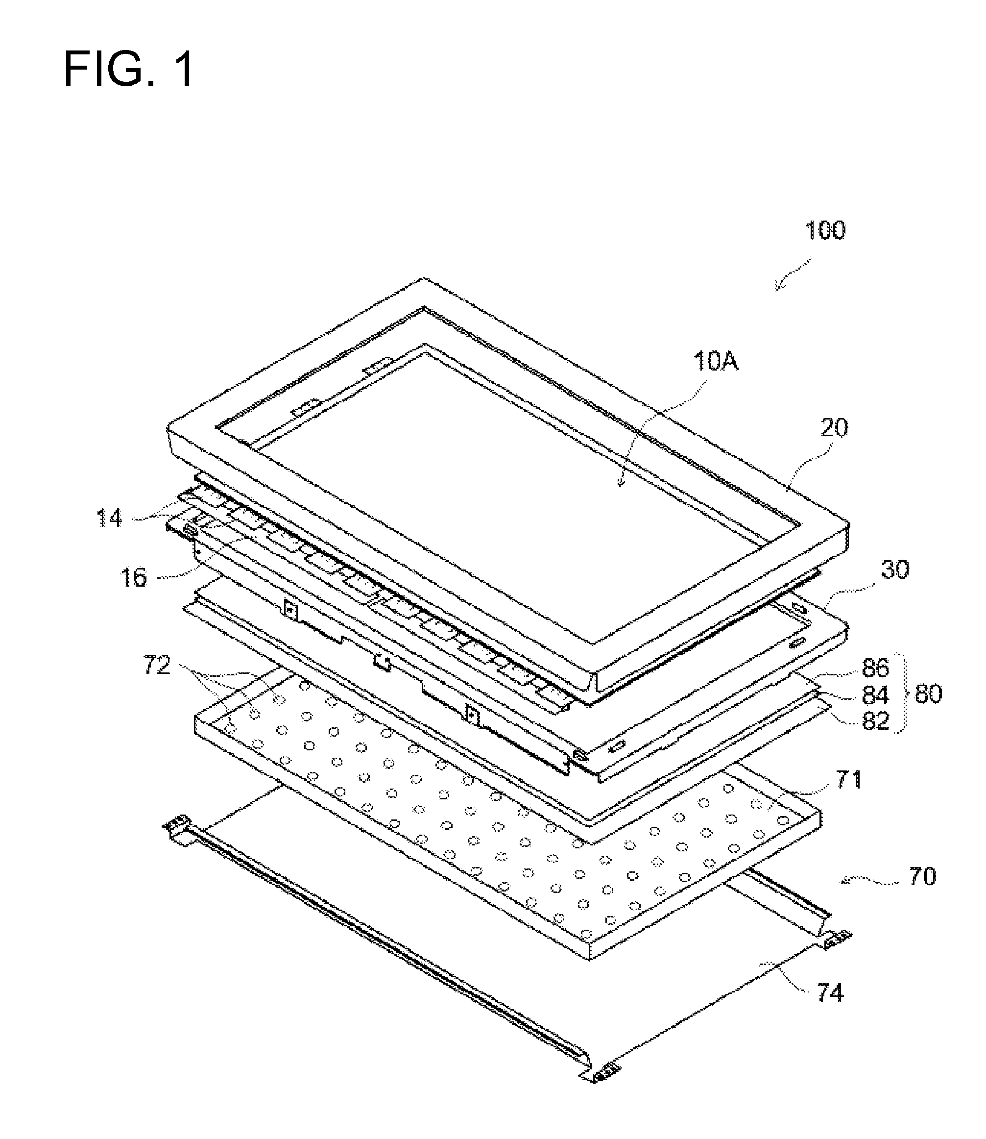
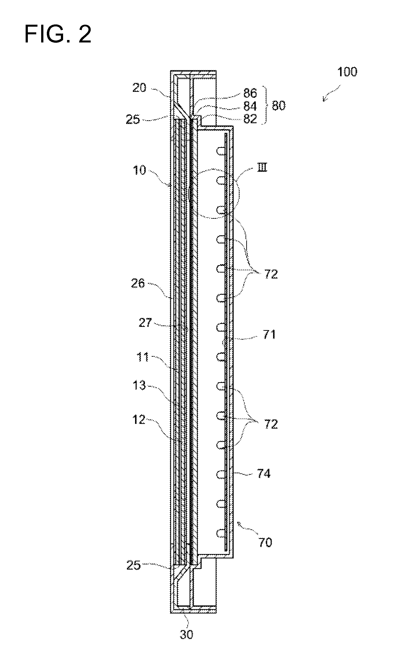
[0039]First, an active matrix type (TFT type) liquid crystal display device 100 including a liquid crystal panel 10 according to a preferred embodiment of the present invention is explained. In the figures hereinafter, the same reference characters are given to membe...


PUM


Abstract

An object of the present invention is to provide a liquid crystal display device capable of uniformly irradiating the entire liquid crystal panel with light (that is, capable of preventing light irradiation non-uniformity that can be recognized by viewers), without excessively increasing the number of point light sources (LEDs). In the liquid crystal display device of the present invention, in a backlight substrate region where a plurality of point light sources (L1 to L8) are disposed in a grid arrangement pattern, a position which is within a virtual rectangular region surrounded by four adjacent point light sources, and which is furthest from each of the adjacent point light sources is defined as an anisotropy reference position (G1 to G3). Light emitted from the point light source closest to the anisotropy reference position is selectively diffused in a direction toward the reference position (G1 to G3) by the anisotropic optical member (82), thereby realizing the optical anisotropy is that direction.

Description

TECHNICAL FIELD[0001]The present invention relates to a liquid crystal display device having a plurality of point light sources as a light source. The present application claims priority to Patent Application No. 2009-070803 filed in Japan on Mar. 23, 2009, and the entire contents of which are hereby incorporated by reference.BACKGROUND ART[0002]Liquid crystal display devices having a liquid crystal panel capable of providing high-definition color images with low power consumption are used for various applications (such as home televisions, mobile phones, and personal computers, for example) as display devices displaying videos and images. Because a liquid crystal element constituting a liquid crystal panel is a non-self light emitting element, in order to improve the luminance of a panel, a backlight device including light sources in various forms is installed in a liquid crystal display device.[0003]As one example of such a back light device, a backlight device provided with a plu...

Claims


Application Information

Patent Timeline
IPC IPC(8): G02F1/1335
CPCG02F1/133603G02F2001/133613G02F2001/133607G02F1/133611G02F1/133613G02F1/133607
Inventor ASAMIZU, TOMOHIRO
Owner SHARP KK
Why Eureka
Try Eureka