
Method Of Calibrating A Lithographic Apparatus, Device Manufacturing Method and Associated Data Processing Apparatus and Computer Program Product

a lithographic apparatus and manufacturing method technology, applied in the field of method for calibrating a lithographic apparatus, can solve the problems of high cost of interruption of production using these expensive tools, users currently have to weigh up the benefits of the stability module, and the cost of this extra calibration step, so as to reduce the throughput penalties of calibration procedures, reduce the cost of calibration materials, and reduce the effect of productivity disruption

Active Publication Date: 2012-01-12
ASML NETHERLANDS BV
View PDF20 Cites 185 Cited by
  • Summary
  • Abstract
  • Description
  • Claims
  • Application Information

AI Technical Summary

Benefits of technology

[0009]Embodiments of the present invention aim to enable improved calibration of lithographic apparatus of the type described above, for example to reduce the throughput penalties of calibration procedures and / or stability monitoring, and / or to reduce the cost of calibration materials used in such procedures. Some embodiments of the present invention integrate a stability monitoring process and a calibration process in such a manner that productivity is less disrupted.

Problems solved by technology

Given that any interruption of production using these expensive tools is very costly, users currently have to weigh up the benefits of the stability module against the cost of this extra calibration step.
Another loss in productivity arises when the monitor wafer wears out and a new monitor wafer must be made with high accuracy.
Further, there is the overhead and risk attached to the need for monitor wafers to be made and maintained with specific tools, in a facility where several tools may be operating side-by-side.

Method used


Image

  • Method Of Calibrating A Lithographic Apparatus, Device Manufacturing Method and Associated Data Processing Apparatus and Computer Program Product
  • Method Of Calibrating A Lithographic Apparatus, Device Manufacturing Method and Associated Data Processing Apparatus and Computer Program Product
  • Method Of Calibrating A Lithographic Apparatus, Device Manufacturing Method and Associated Data Processing Apparatus and Computer Program Product

Examples


first embodiment

Calibration and Stability Control—First Embodiment of New Method

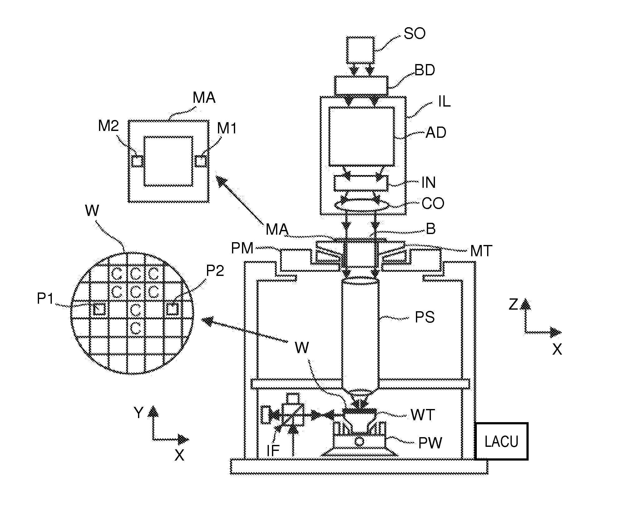
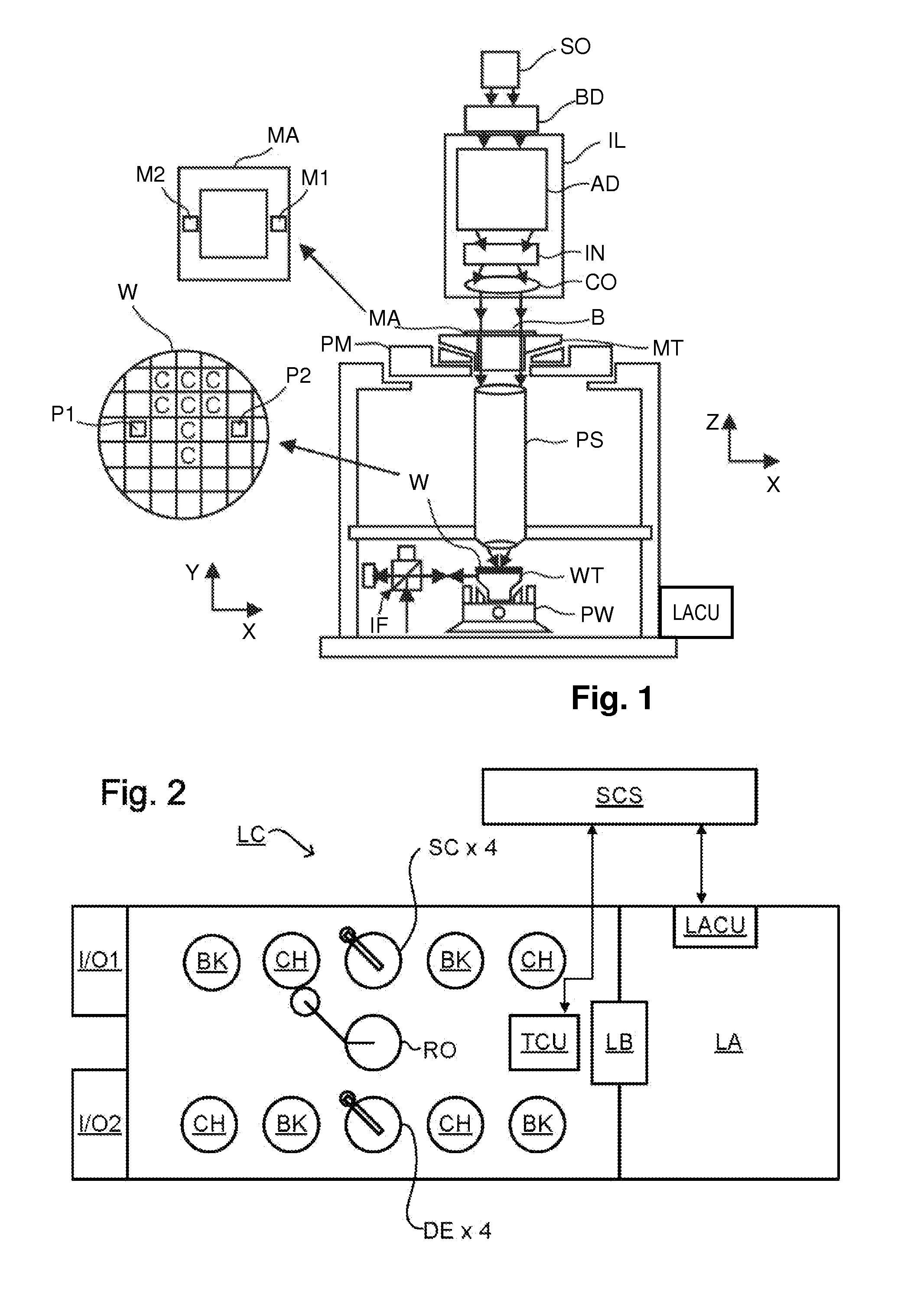
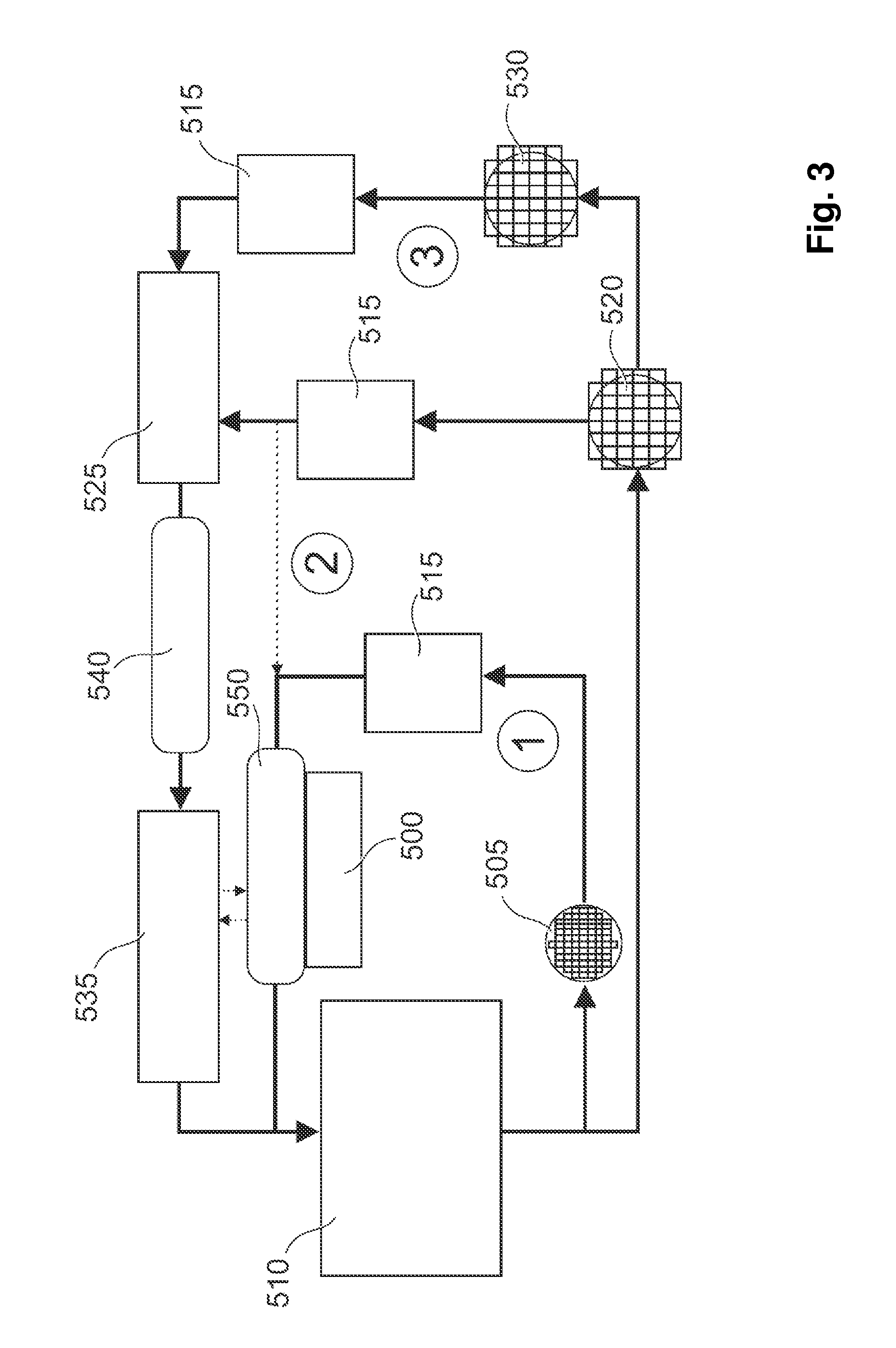
[0071]FIG. 5 illustrates one example of a new method in which calibration and stability control processes of the type described above are integrated in such a manner that interruptions to production can be reduced greatly, and in which matching of machines can be performed in fewer steps and with fewer logistical restrictions than by the methods of FIG. 4. The new method can be implemented using the same apparatuses as described already with reference to FIGS. 1 to 3, simply by modification of control software and data structures in the control unit LACU. Other embodiments of the new method, with respective advantages and disadvantages, will be described in a separate section, below.

[0072]Process 700 replaces the machine set-up process 600 for routine operation of the tools (setup processes of the conventional kind will of course be required in the course of installation and major maintenance). A tool is selected, for e...


PUM


Abstract

A lithographic apparatus is calibrated by reference to a primary reference substrate. Using an apparatus which need not be the same as the one being calibrated, there is obtained an apparatus-specific fingerprint of the primary reference substrate. Using the same set-up there is then obtained an apparatus-specific fingerprint of a secondary reference substrate. The apparatus-specific fingerprint of the primary reference substrate is subtracted from the apparatus-specific fingerprint of the secondary reference substrate to obtain and store an apparatus-independent fingerprint of the secondary reference substrate. The secondary reference substrate and stored apparatus-independent fingerprint are subsequently used together in place of the primary reference substrate as a reference for the calibration of the lithographic apparatus to be calibrated. Initial set-up for a cluster of lithographic tools can be performed with less use of the costly primary reference substrate, and with less interruption to normal production. The initial set-up can be integrated with on-going monitoring and re-calibration of the apparatuses.

Description

CROSS REFERENCE TO RELATED APPLICATIONS[0001]This application claims benefit under 35 U.S.C. 119(e) to U.S. Provisional Application No. 61 / 362,901, filed Jul. 9, 2010, which is incorporated by reference herein in its entirety.BACKGROUND OF THE INVENTION[0002]1. Field of the Invention[0003]The present invention relates to a method for calibrating a lithographic apparatus. The present invention further relates to methods of manufacturing devices using lithographic apparatus calibrated by such a method, and to data processing apparatuses and computer program products for implementing parts of such a method.[0004]2. Background Art[0005]A lithographic apparatus is a machine that applies a desired pattern onto a substrate, usually onto a target portion of the substrate. A lithographic apparatus can be used, for example, in the manufacture of integrated circuits (ICs). In that instance, a patterning device, which is alternatively referred to as a mask or a reticle, may be used to generate ...

Claims


Application Information

Patent Timeline
IPC IPC(8): G03B27/32G06K9/00
CPCG03F7/70516G06K9/3216G06T7/0018G06T2207/30148G06T2207/10004G06T2207/10061G06T2207/20224G06T7/0042G06T7/80G06T7/73G06V10/245
Inventor TEL, WIM TJIBBOPRIL, WOUTER ONNOTHEEUWES, THOMASPADIY, ALEXANDER VIKTOROVYCH
Owner ASML NETHERLANDS BV
Learn More