Endoscope apparatus

a technology of endoscope and endoscope insertion, which is applied in the field of endoscope apparatus, can solve the problems of reducing the diameter of the endoscope insertion portion, affecting the accuracy of endoscope insertion, so as to achieve good space efficiency, prevent the generation of uneven radiation, and high accuracy

Inactive Publication Date: 2012-01-12
FUJIFILM CORP
View PDF11 Cites 144 Cited by
  • Summary
  • Abstract
  • Description
  • Claims
  • Application Information

AI Technical Summary

Benefits of technology

[0011]With the above endoscope apparatus, the irradiation windows of the first irradiation portion, which radiate the white light, and the irradiation windows of the second irradiation portion, which radiate the narrow bandwidth lights, are disposed at such positions on the leading end surface of the endoscope insertion portion where good space efficiency can be provided and generation of uneven radiation can be prevented. Also, the spectra of the narrow bandwidth lights emitted from the respective irradiation windows of the second irradiation portion can be controlled individually. Thereby, the narrow bandwidth lights having the different spectra can be emitted simultaneously from the respective irradiation windows of the second irradiation portion. Therefore, in addition to a normal observation under white light illumination and a special light observation using the narrow bandwidth light, the narrow bandwidth lights having the different spectra can be radiated. Thereby, multipurpose diagnosis can be realized with high accuracy.

Problems solved by technology

In the case where the irradiation window is disposed improperly with respect to the observation window, when an area to be observed has unevenness, it cannot be radiated uniformly, with the result that uneven radiation or shadow would appear in the observation image.
In this structure, in the case where multiple irradiation windows are to be disposed in the leading end of the endoscope insertion portion, a space for the irradiation windows might occupy much space, which would be disadvantageous in reducing the diameter of the endoscope insertion portion.
However, depending on the position relationship between the irradiation windows and observation window, uneven radiation would be easy to occur.
However, especially, when a moving image is displayed, in some cases, the frame rate might be slowed down and thus the display quality would be deteriorated.

Method used


Image

  • Endoscope apparatus
  • Endoscope apparatus
  • Endoscope apparatus

Examples


Embodiment Construction

[0044]Now, description will be given below specifically on embodiments of the invention with reference to the accompanying drawings.

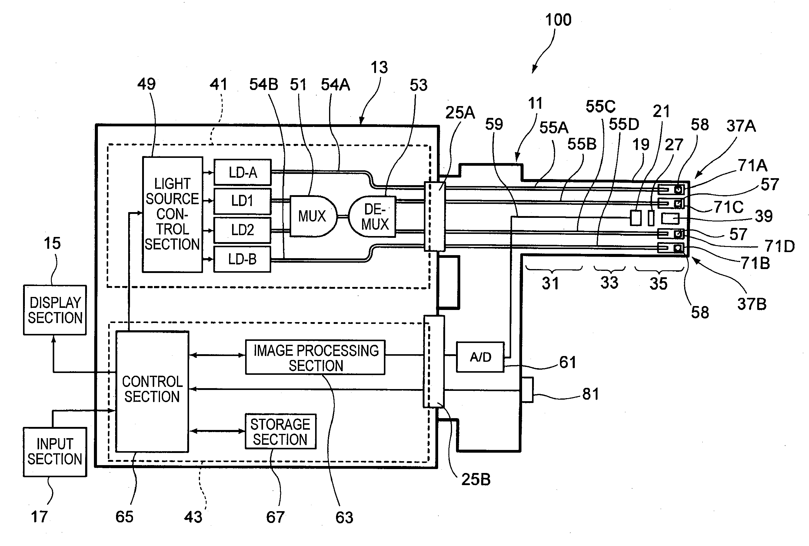
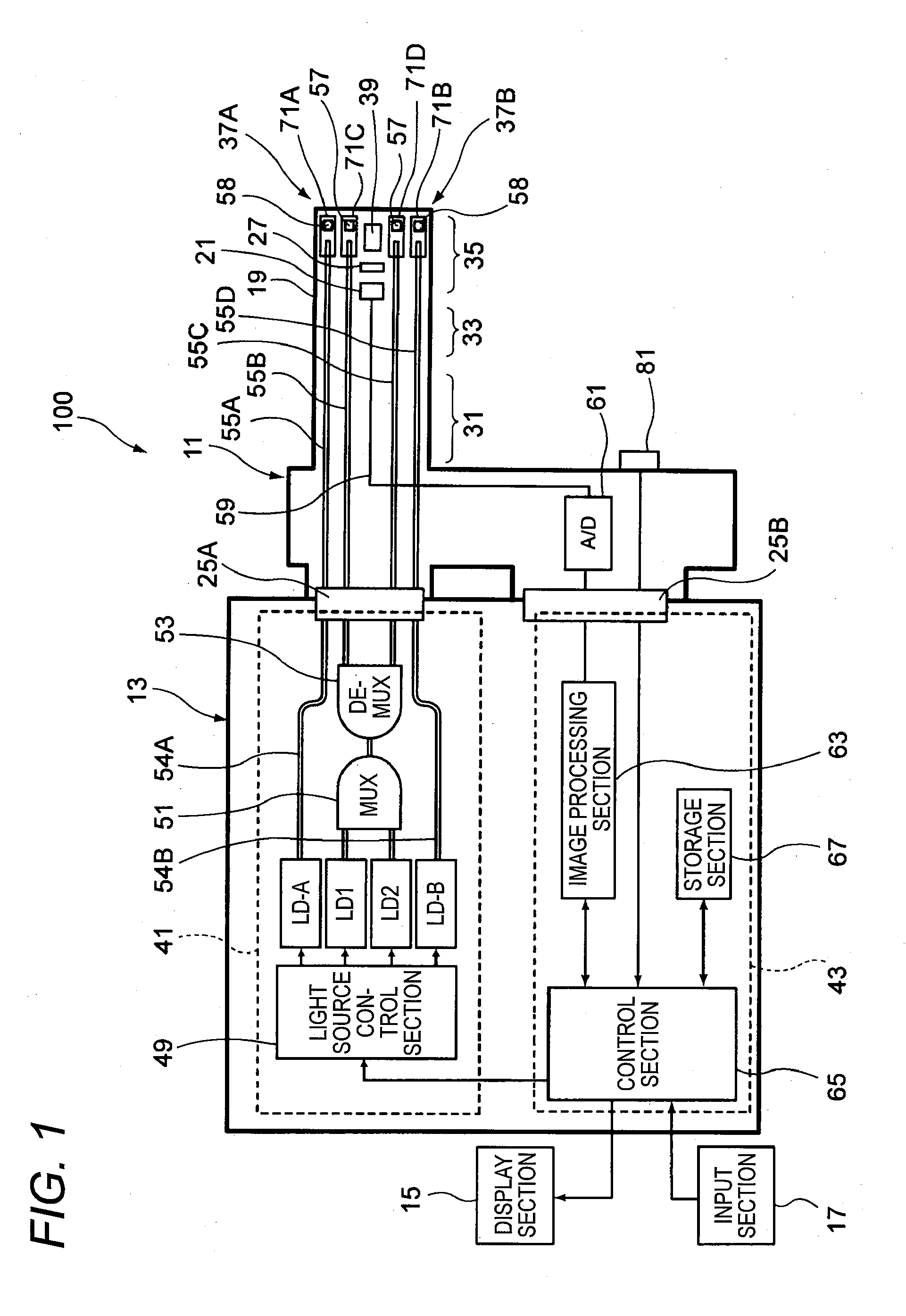
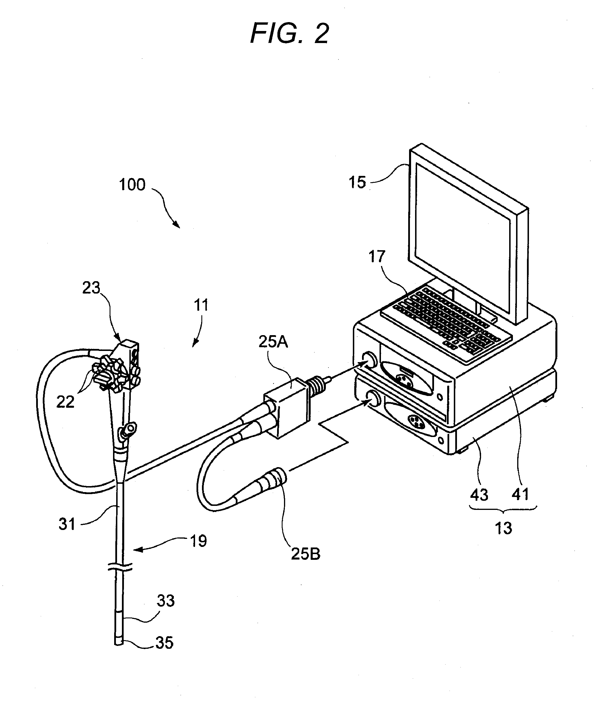
[0045]FIG. 1 is an explanatory view a schematic block diagram of the configuration of an endoscope apparatus according to an embodiment of the invention. FIG. 2 is an appearance view of an example of the endoscope apparatus shown in FIG. 1.

[0046]As shown in FIGS. 1 and 2, an endoscope apparatus 100 includes an endoscope 11, a control apparatus 13 to which the endoscope 11 is connected, a display section 15 for displaying image information and the like thereon, and an input section 17 for accepting an input operation. The endoscope 11 is an electronic endoscope which includes a illumination optical system for emitting illumination light from a leading end of an endoscope insertion portion 19 to be inserted into a subject, and an imaging optical system having an imaging device 21 (see FIG. 1) for capturing an image of an area to be observed.

[0047]The endo...


PUM


Abstract

A first irradiation portion that radiates white light onto a subject, a second irradiation portion that radiates narrow bandwidth light having a narrower wavelength bandwidth than the white light, and an observation window used to observe the subject are respectively disposed on a leading end surface of an endoscope insertion portion. Each of the first and second irradiation portions includes a pair of irradiation windows for emitting light therefrom. A straight line passing through a center point of the observation window and bisecting the leading end surface is defined as a boundary line. The pair of irradiation windows of the first irradiation portion are disposed on both sides of the boundary line. The pair of irradiation windows of the second irradiation portion are disposed on the both sides of the boundary line. Spectra of lights radiated from the irradiation windows of the second irradiation portion can be changed individually.

Description

CROSS-REFERENCE TO RELATED APPLICATIONS[0001]This application claims the benefit of Japanese Patent Application No. 2010-157357, filed Jul. 9, 2010, the entire contents of which are hereby incorporated by reference, the same as if set forth at length.BACKGROUND OF THE INVENTION[0002]1. Technical Field[0003]The present invention relates to an endoscope apparatus.[0004]2. Description of the Related Art[0005]Generally, an endoscope apparatus is configured such that an irradiation window and an observation window are respectively disposed in the leading end of an endoscope insertion portion to be inserted into a body cavity, illumination light is radiated from the irradiation window, and an image of a portion to be observed within the body cavity is captured through the observation window. Then, the thus obtained observation image is displayed on a monitor screen to perform an endoscopic diagnosis for the portion to be observed. Examples of the illumination light include white light emi...

Claims


Application Information

Patent Timeline
Patent Type & Authority Applications(United States)
IPC IPC(8): A61B1/04A61B1/06
CPCA61B1/05A61B1/0638A61B1/0646A61B1/0653A61B1/07A61B1/043A61B1/063A61B1/0669A61B1/0655
Inventor ERIKAWA, AKIHIKOOZAWA, SATOSHIIIDA, TAKAYUKI
Owner FUJIFILM CORP
Why Eureka
Try Eureka