Model verification system, model verification method, and recording medium

a verification system and model technology, applied in the field of model verification systems and model verification methods, can solve problems such as inability to quantitatively determine the effects of a program change, system does not actually carry out refactoring, and improper evaluation of modified programs

Active Publication Date: 2012-01-12
NEC CORP
View PDF7 Cites 17 Cited by
  • Summary
  • Abstract
  • Description
  • Claims
  • Application Information

AI Technical Summary

Problems solved by technology

However, the system disclosed in Patent Document 1 has a problem that the refactoring rule is personalized such that optimized models vary depending upon the consultant.
Furthermore, this system does not actually carry out refactoring as a program.
Additionally, effects caused by a change of a program cannot be determined quantitatively.
Furthermore, the system disclosed in Patent Document 2 does not take into consideration, optimization of a generated conversion rule or optimization of a program to which a conversion rule has been applied.
The modified program is not properly evaluated with regard to many items such as reduction of resources or reduction of a processing time as descried above.

Method used


Image

  • Model verification system, model verification method, and recording medium
  • Model verification system, model verification method, and recording medium
  • Model verification system, model verification method, and recording medium

Examples


example 1

[0169]Next, an operation of the first embodiment will be described along with specific examples.

[0170]Description is made about an operation of the first embodiment which may be called

[0171]Example 1 and in which the model figure is a sequence diagram of UML, the formal language expression is an XML schema, and the information description expression is XML.

[0172]FIG. 25 is an explanatory diagram schematically showing increment and quantification of a schema in Example 1. In the example of FIG. 25, it is assumed that parameters are extracted such that the service components are A, B, and C, and that B, C, and A are sequentially called in the calling order. Furthermore, it is assumed that a period of time for a consecutive process starting at B and ending at A is 50 ms.

[0173]The model verification system converts a sequence diagram, which is given as an input, into a formal language expression in the XML schema format according to the correspondence table. The XML schema indicating th...

example 2

[0209]A second example of the present invention in which model figures are expressed in the BPEL language will be described along with specific values with reference to FIGS. 29 and 30.

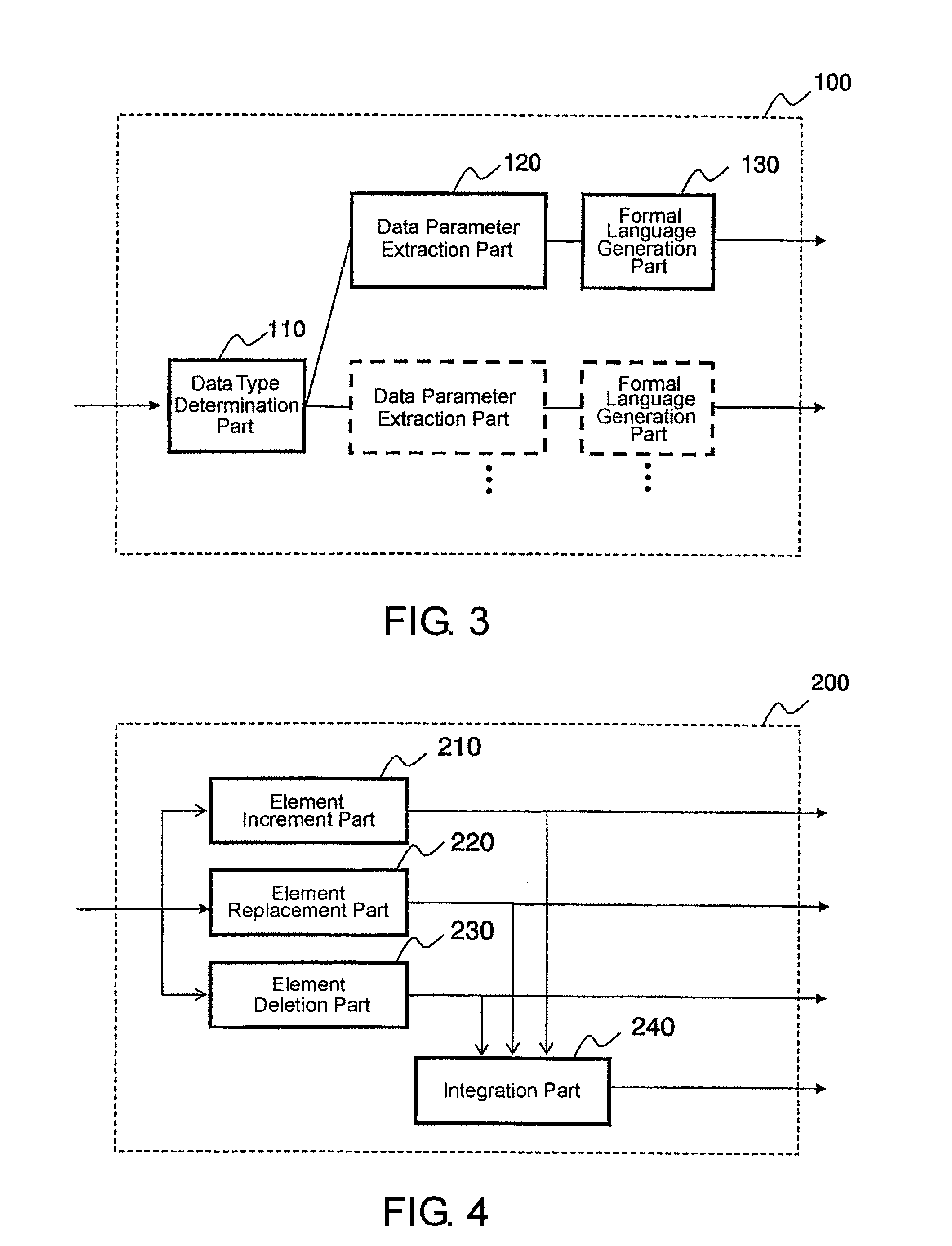
[0210]First, the data type determination part 110 collates an extension “.seq” of a file with the correspondence table of FIG. 23 (Step S101) to determine whether or not the file can be managed.

[0211]If the file is manageable, the data parameter extraction part 2120 extracts parameters of the service components, the interfaces, and the calling order from a sequence diagram (Step S103).

[0212]In the example of FIG. 29, there are extracted parameters of the service components A, B, and C, the interfaces op1, op2, and op3, and the calling order in which a call from A to B and a call from A to C are made in parallel.

[0213]When those parameters are provided to the information expression generation part 2330 (see FIG. 28), an information expression in the BPEL format is acquired. The acquired information exp...

example 3

[0215]A third example of the present invention in which an XPath form is used in the formal language expression will be described along with specific values.

[0216]FIG. 31 is an explanatory diagram schematically showing increment of an XPath form in Example 3. In the example of FIG. 31, it is assumed that parameters are extracted such that the service components are A, B, and C, and that B, C, and A are sequentially called in the calling order.

[0217]The model verification system converts a sequence diagram, which is an input, into a formal language expression in the XPath format according to the correspondence table (see FIG. 33). The XPath form indicating the order of B, C, and A is as follows. FIG. 31 only illustrates a primary portion.

/ descendant::B / following-sibling::C / following-sibling::A

[0218]Then a formal language increment is performed with respect to this standard XPath form so as to generate a derivative XPath form as formal language expression data of a derivative design.

[...


PUM


Abstract

A model verification system includes a formal language conversion part operable to convert model figure data registered as a design pattern in association with a program into formal language expression data based upon an expression format of a predetermined formal language, and a formal language increment part operable to add a modification to a component of the formal language and / or attribute information on the formal language expression data converted by the formal language conversion means to generate formal language expression data of a derivative design. The model verification system conducts refactoring.

Description

TECHNICAL FIELD[0001]The present invention relates to a model verification system, a model verification method, and a program for a model verification system to verify a design of a program accumulated as a model. More specifically, the present invention relates to a model verification system, a model verification method, and a model verification program for verifying a design of a program with use of model figure data represented by a human visible form.BACKGROUND ART[0002]In recent years, a development technique of automatically generating a program from models has been known under the name of the model-driven architecture. With this development technique, a system developer (programmer) can program, without learning a description method using characters of a programming language, by combining predetermined figure expressions into a series of process flows.[0003]A figure expression used in the above model-driven architecture represents an assigned process in a visually comprehensi...

Claims


Application Information

Patent Timeline
Patent Type & Authority Applications(United States)
IPC IPC(8): G06F9/44
CPCG06F11/3608G06F8/20G06F8/72G06F11/3668
Inventor MATSUMOTO, SHIGEAKI
Owner NEC CORP
Why Eureka
Try Eureka