
Button-Fixing Member

a button fixing and button technology, applied in the field of button fixing members, can solve the problems of poor fabric piercing (or fabric piercing) property, poor fabric piercing property, and defective piercing of cloth threads by the post, etc., to achieve less rigid resistance, easy to collapse axially, and better fabric piercing property

Inactive Publication Date: 2012-01-19
YKK CORP
View PDF8 Cites 5 Cited by
  • Summary
  • Abstract
  • Description
  • Claims
  • Application Information

AI Technical Summary

Benefits of technology

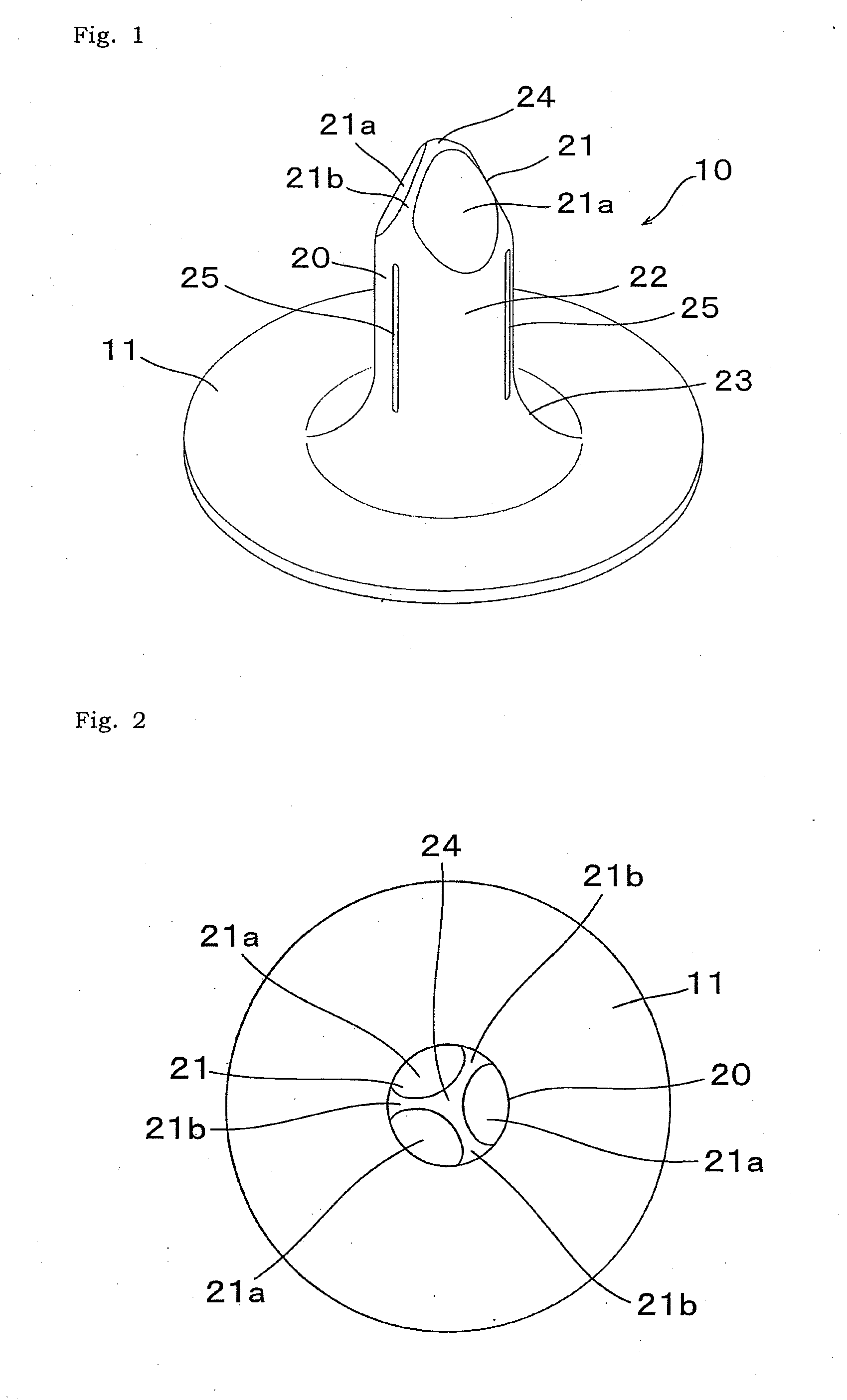
[0005]In the invention, since the post top of the button-fixing member is a triangular pyramid-shaped or a quadrangular pyramid-shaped, the post top can cleave a cloth (the sheet material) intensively at the three or four ridge portions at circumferential intervals of 120 or 90 degrees, the ridge portions corresponding to the ridges of a triangular or quadrangular pyramid. Therefore, as compared to a cone-shaped post top, the post top has a better fabric-piercing property, can reduce fabric-piercing defects even in a fabric with relatively easily entrained threads, and the post is less likely to incline with respect to the base at piercing a cloth.
[0006]Further, in the invention, when the post of the button-fixing member is compressed by a die and the like to fix a button to a cloth, a force to compress the post is transmitted from the projecting end of the post through the post top to the post barrel. At this moment, the force is conveyed from the post top to the post barrel via the ridge portions rather than the pyramid-element faces in the top post. This is because the ridge portions can function as a shell frame of the post top. The force via the ridge portions is transmitted, firstly to the regions in the post barrel axially adjacent to the ridge portions. The regions including the dents are less rigid in resistance to axial buckling due to the dents, in which the dents are formed, so the dent including regions at circumferentially 120 or 90 degree intervals are tend to more easily collapse axially and extend radially outward larger than the remaining parts between circumferentially adjacent dents and without dents.
[0009]In the invention, since the post top of the button-fixing member is a triangular pyramid-shaped or a quadrangular pyramid-shaped, a better fabric-piercing property can be obtained, and there is less likely to cause fabric-piercing defects. Further, since the regions, in which the dents are formed, in the post barrel circumferentially corresponding to the ridge portions of the post top are less rigid in resistance to axial buckling, a force to compress the post, which is transmitted mainly via the ridge portions to the barrel post, is received at the dent including region at circumferentially 120 or 90 degree intervals, and therefore the dent including regions at circumferentially 120 or 90 degree intervals can relatively easily collapse axially and extend radially outward larger. As a result, there is less likely to cause the post to collapse in a circumferentially biased form and bring about a defective fixing of a button.

Problems solved by technology

On the other hand, a hollow post type button-fixing member is difficult to sharpen the tip of its post compared to the solid type member.
Therefore, a hollow type member may have a poor fabric-penetrating (or fabric-piercing) property depending on a variety of cloths, which would lead to a defective piercingness with threads of a cloth entrained by the post.
Further, in a hollow post type button-fixing member, the post may be likely to incline with respect to the base at piercing a cloth.
Furthermore, with the hollow post type, there is a possibility that the post does not collapse uniformly in the circumferential direction when the post, after piercing a cloth, is swaged by a fixing die (or a part of a button) to fix a button on the cloth, because a force for swaging the post is difficult to be transmitted radially uniformly in the post from its tip to the base (proximal) side.
This problem may become more significant when the post inclined with respect to the base at piercing a cloth as mentioned above.
This defective collapse (buckling) of the post can make the button easy to come off the cloth, and harm the appearance of a fixed button depending on a variety of buttons, leading to a defective fixing.

Method used


Image

  • Button-Fixing Member
  • Button-Fixing Member
  • Button-Fixing Member

Examples


Embodiment Construction

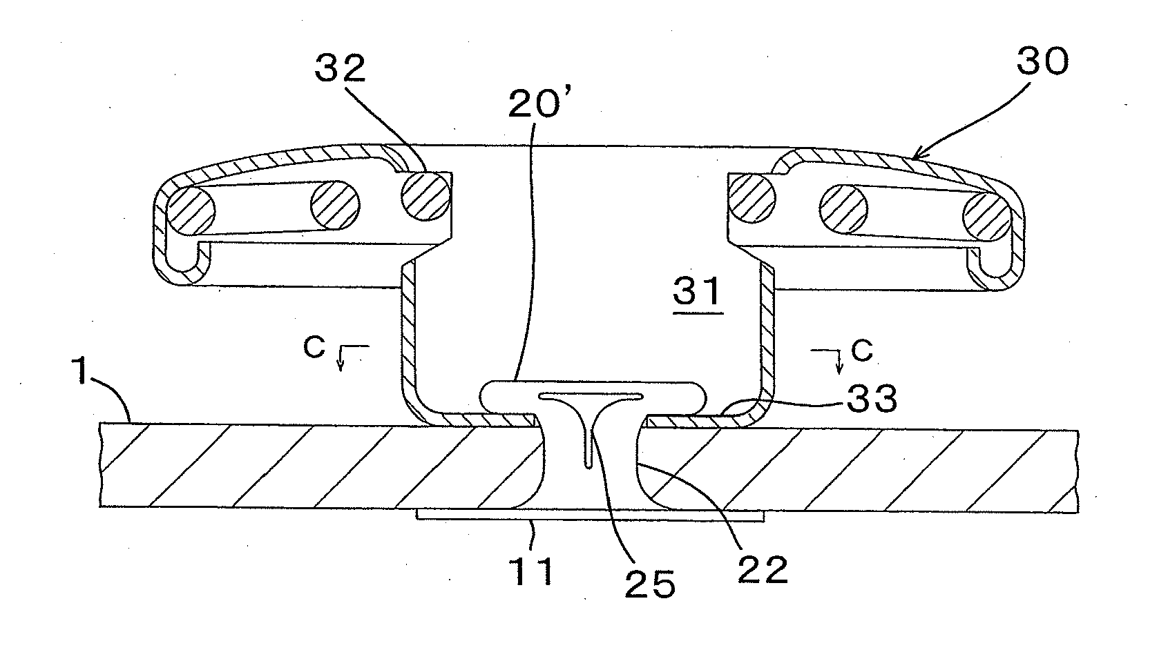
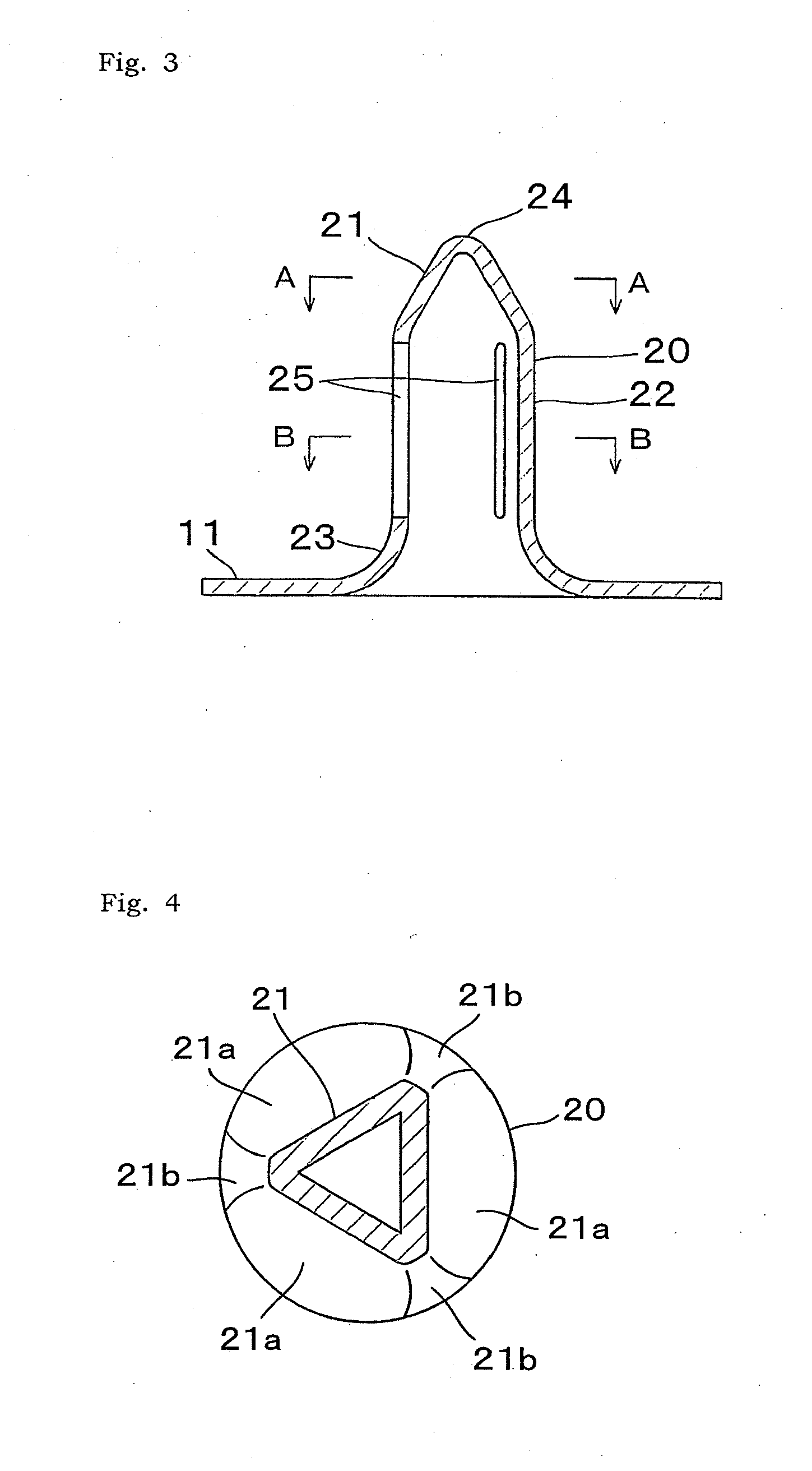
[0023]Hereinafter, preferred embodiments of a button-fixing member according to the invention will be described with reference to the drawings. FIG. 1 is a perspective view of a button-fixing member 10 according to an embodiment of the invention. FIGS. 2 and 3 are a plane view (or a top view) and a longitudinal sectional view (along one of after-mentioned slits (dents) 25) of the button-fixing member 10, respectively. FIGS. 4 and 5 are lateral sectional views respectively along line A-A and line B-B of FIG. 3. The button-fixing member 10, which is formed by drawing a single metal plate, includes a disk-like base 11 and a hollow post 20 which is projected upward from and coaxially with the base 11 at its center area. The projecting end 24 of the post 20 is closed. The post 20 includes a triangular pyramid-shaped post top 21 and a cylindrical post barrel 22. The post top 21 has, at its tip, the projecting end 24. The cylindrical post barrel 22 extends between the post top 21 and the b...


PUM

PropertyMeasurementUnit
thicknessaaaaaaaaaa
forceaaaaaaaaaa
resistanceaaaaaaaaaa

Abstract

The invention is to provide a button-fixing member including a hollow post, in which the post has a better fabric-piercing property and therefore is less likely to cause a defective piercing, a poor collapse of the post or a poor fixing of a button. The button-fixing member according to the invention includes a base and a post. The post is hollow and includes a triangular pyramid-shaped or quadrangular pyramid-shaped post top and a cylindrical post barrel which extends between the post top and the base. The post top has three or four pyramid-element faces and three or four ridge portions between the pyramid-element faces. The post barrel has slits or grooves which are elongated in the axial direction at the positions circumferentially corresponding to the ridge portions.

Description

BACKGROUND OF THE INVENTION[0001]The invention relates to a button-fixing member, and more particularly, to a button-fixing member for fixing a button such as a snap button and a decorative button onto a cloth and the like for clothing or bags.[0002]In general, a button-fixing member such as a rivet has been used as a component to fix a button onto a cloth such as clothing. The button-fixing member has a disk-like base, and a post projecting from a center portion of the base, and the button-fixing member is used to fix a button to a cloth by swaging the post which has pierced the cloth. Such a button-fixing member includes one with a solid post (see e.g. Japanese Utility-model Application Laid-open No. S59-128210 etc.) and one with a hollow post (see e.g. Japanese Utility-model Application Laid-open No. S62-164806). The button-fixing member with a hollow post is typically formed by drawing a single metal plate, and has higher buckling deformability and a smaller pressing force requi...

Claims


Application Information

Patent Timeline
Patent Type & Authority Applications(United States)
IPC IPC(8): B23P23/04
CPCY10T29/51A44B1/44
Inventor HASEGAWA, KENJI
Owner YKK CORP
Learn More