
Counter for a Drug Dispenser

Inactive Publication Date: 2012-01-19
BARI NASEEM
View PDF16 Cites 29 Cited by
  • Summary
  • Abstract
  • Description
  • Claims
  • Application Information

AI Technical Summary

Benefits of technology

[0024]The design herein shows a design that is relatively simple to manufacture while allowing the battery to be replaceable and also retain the count with the canister instead of the housing. It contains a feature that when it is shaken, a motion sensor will be activated and it will initiate an indication of the status of the amount of drug remaining in the canister
[0029]The design is based on indicating its use by visual means of either a Liquid crystal display (LCD) or preferably a light emitting diode (LED) form when the user uses the inhaler to administer the drug. The display is not limited to electrical means but can also be a mechanical view adjusted by a set of wheels to display the count value. The means of saving power for giving the status of the unit a vibration sensor is used to detect severe side force which will cause an internal electrical contact to be made and so initiate an indication of the LEDs or LCD to display the current usage of the indicator. This technique allows the non use of an external switch keeping the electronics isolated from the external user. It also prevents the drainage of the battery as it will always require a force to cause the indication as a result nothing will happen if it is stationary.

Problems solved by technology

This is the problem that exists.
Once the inhaler canister is detached from the housing and mixed with other canisters, for example, to wash the mouth piece out or clean the canister nozzles, there is no means of being able to determine the number of uses that particular canister has left, especially when it is mixed in with other canisters of the same type.
Keeping count of which canister is still with drugs inside can be a problem.
This could be a potentially serious problem for the patient, resulting in an emergency when they find that the drug in their inhaler had been exhausted by an earlier use.
This can cause more anxiety and lead to more emotional distress.
These devices suffer from the problem that they either have to be reset manually, or if a canister is removed from the inhaler, the counter automatically resets, so if the same canister is replaced (e.g. after cleaning), the reading will be incorrect.
However most of these also still have the problem that the count of the drug remains with the housing rather than the canister thus making the design have the same problem that the user still does not know how much is left in the canister should they swap it for another.
These devices can use different techniques but most of them being too costly to manufacture or are too complex in function to allow them to function correctly when mass produced.
While these patents are novel in the technique, non of them consider the impact in manufacturing a solution for the public to use the design sufficiently to provide a reasonably accurate indication of the remaining drug.
It is apparent that major reasons on the lack of designs in the market are precisely because of the cost and complexity of the designs to provide a manufacturability solution.
Again for manufacture assembly it is very complex and difficult making the unit costly and difficult to use.
The problem again is the complexity to achieve the count and again it does NOT hold the count on the canister when it is removed from the housing.
Patent US006202642B1 by Robert J McKinnon shows a very complex design in which the canister is complexly housed in the housing.
Assembly for manufacture is very complex and difficult to use.
This is accurate but complex to manufacture and calibrate for the user.
The problem with most of them is that they use the housing to hold the count information rather than the canister.
This is an acceptable design but it is complex to manufacture.
All of the designs use power from a battery and do not necessarily disclose the replacement of it and some may be subject to being thrown away after use due to the battery expiring.

Method used


Image

  • Counter for a Drug Dispenser
  • Counter for a Drug Dispenser
  • Counter for a Drug Dispenser

Examples


Embodiment Construction

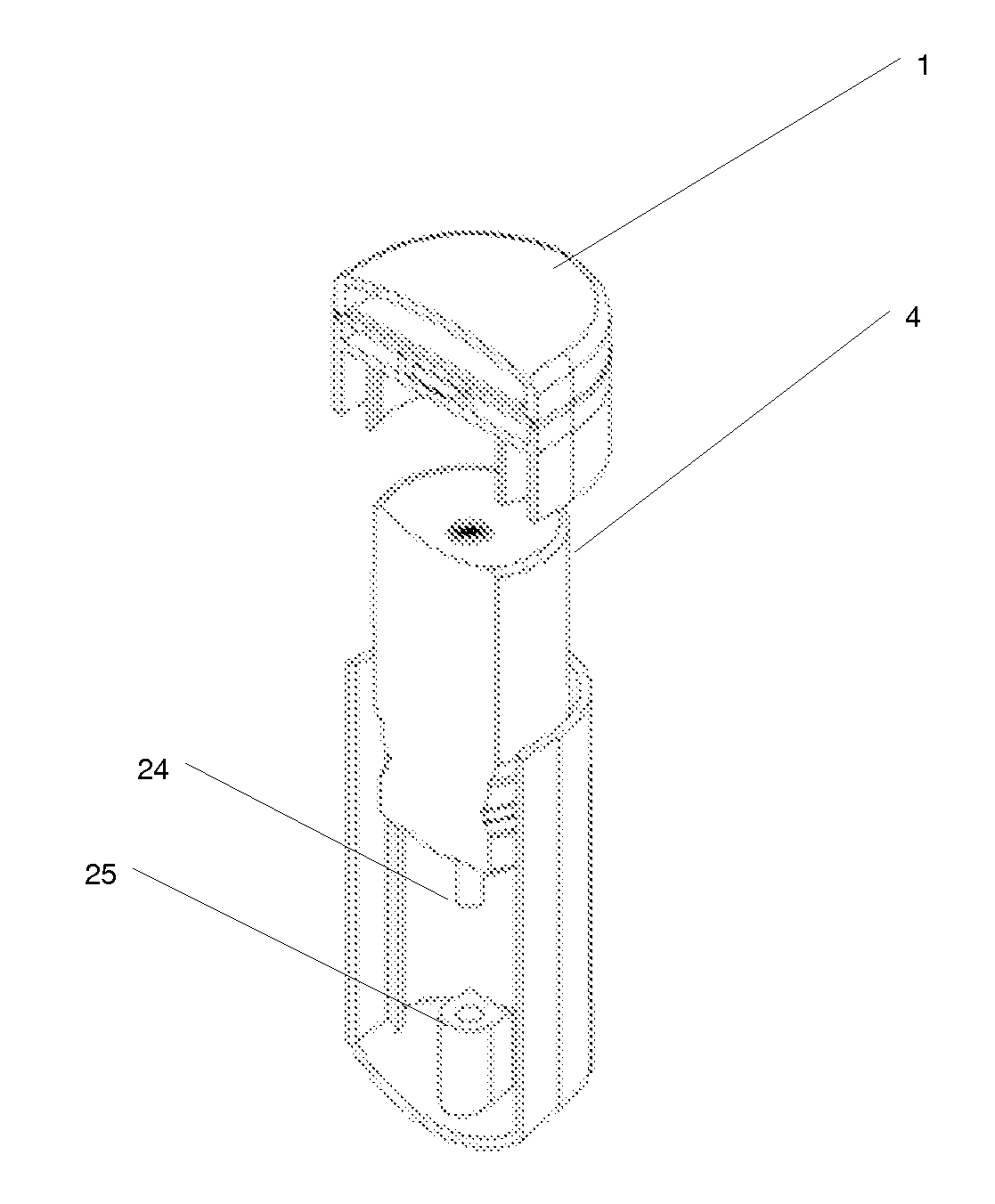
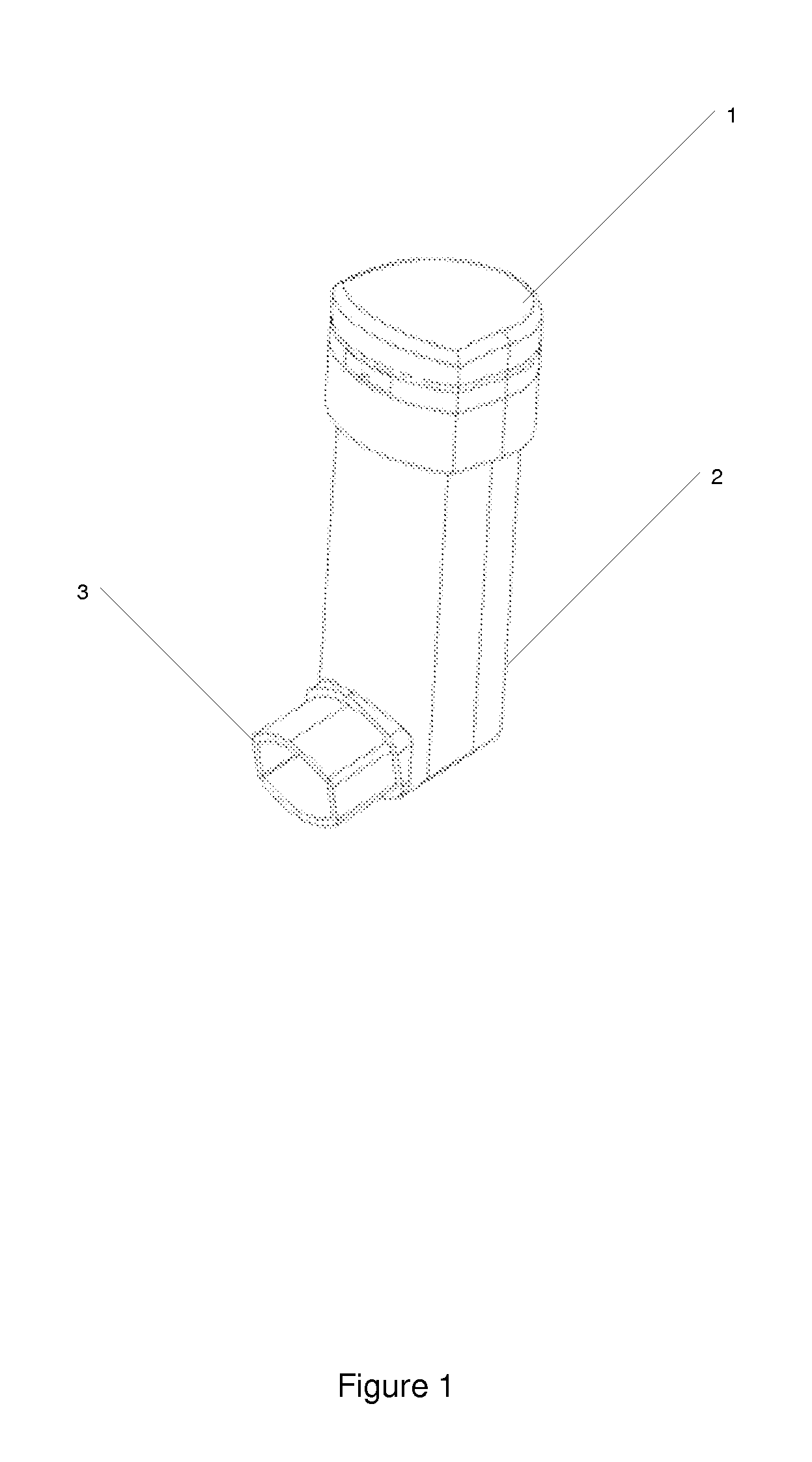
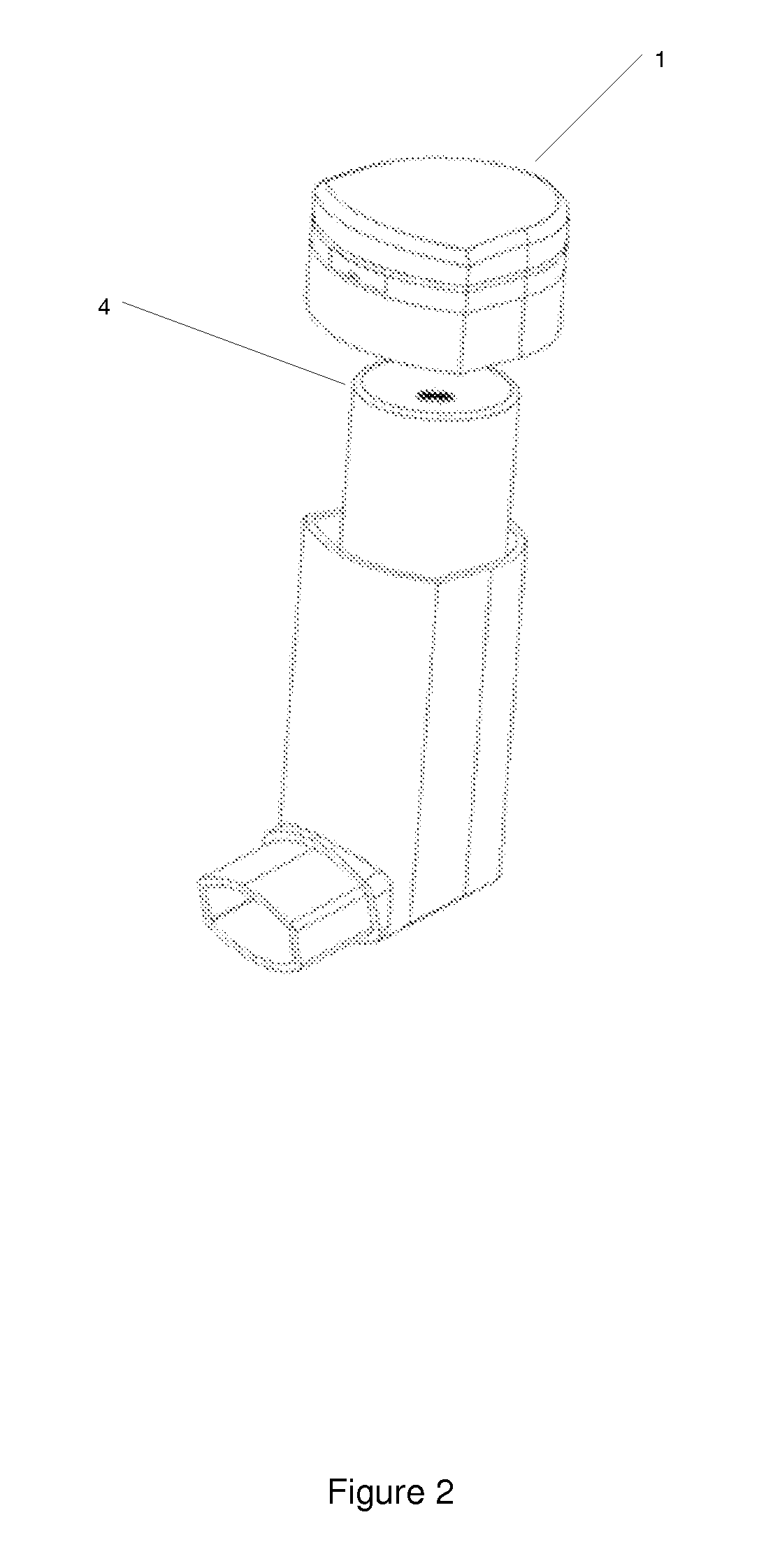
[0039]With Reference to FIG. 1 this shows the fully assembled inhaler unit ready for use. The counter [1] is assembled onto the main housing [2] and in the orientation showing the position of the mouthpiece [3]. FIG. 3 shows the counter [1] removed off the canister [4] which is inserted into the main housing. FIG. 3 shows the section view of the full assembly and indicates the coupling of parts. The canister nozzle [24] is inserted into the main housing actuator [25]. Under normal operation the top part of the counter is depressed and the nozzle is depressed into the actuator until the valve inside the canister releases the drug. The drug then disperses through the mouth piece. In this embodiment the tri colour LED [26] is shown at the top of the counter and that would then light up into the magnified dome [27] to indicate successful drug release and indicate the remaining amount of drug in the canister. The current embodiment is based on a traffic light system such that if the numb...


PUM


Abstract

The invention is for a waterproof Inhaler Usage Indicator with or without a replaceable battery (6), to provide a count of the amount of drug remaining inside the canister (4) with the counter (1) still attached to the canister (4). It is not limited to inhalers alone, but any type of canister (4) that dispenses through a nozzle (24) when placed inside an housing (2) in order to count the number of displacements between the canister (4) and housing (2). The status of the drug can be checked at any time by a quick movement of the inhaler in any axis to allow the motion sensor (40, 41) to initiate the display of the amount of remaining drug uses. The counter assembly (1) is attached to the top of the canister (4) and uses the displacement between the canister (4) and housing (2) to count the number of uses.

Description

[0001]The invention is for a waterproof Inhaler Usage Indicator with or without a replaceable battery, to provide a count of the amount of drug remaining inside the canister with the counter still attached to the canister. It is not limited to inhalers alone, but any type of canister that dispenses through a nozzle when placed inside an housing in order to count the number of displacements between the canister and housing. The status of the drug can be checked at any time by a quick movement of the inhaler in any axis, to allow the motion sensor to initiate the display of the amount of remaining drug uses.BACKGROUND[0002]Inhalers are commonly used to administer medication such as bronchodilators, corticosteroids and anti-allergenics to the pulmonary tracts of humans and other animals, and in particular to treat nasal and bronchial complaints such as asthma.[0003]A typical inhaler includes a canister, having a nozzle, containing the drug or medicine, and a detachable casing for attac...

Claims


Application Information

Patent Timeline
IPC IPC(8): A61M11/00B67D7/22
CPCA61M15/009A61M15/008A61M15/0005A61M2205/8206A61M15/0073
Inventor BARI, NASEEM
Owner BARI NASEEM
Learn More