

Method for production of safety/rupture discs
- Summary
- Abstract
- Description
- Claims
- Application Information
AI Technical Summary
Benefits of technology
Problems solved by technology
Method used
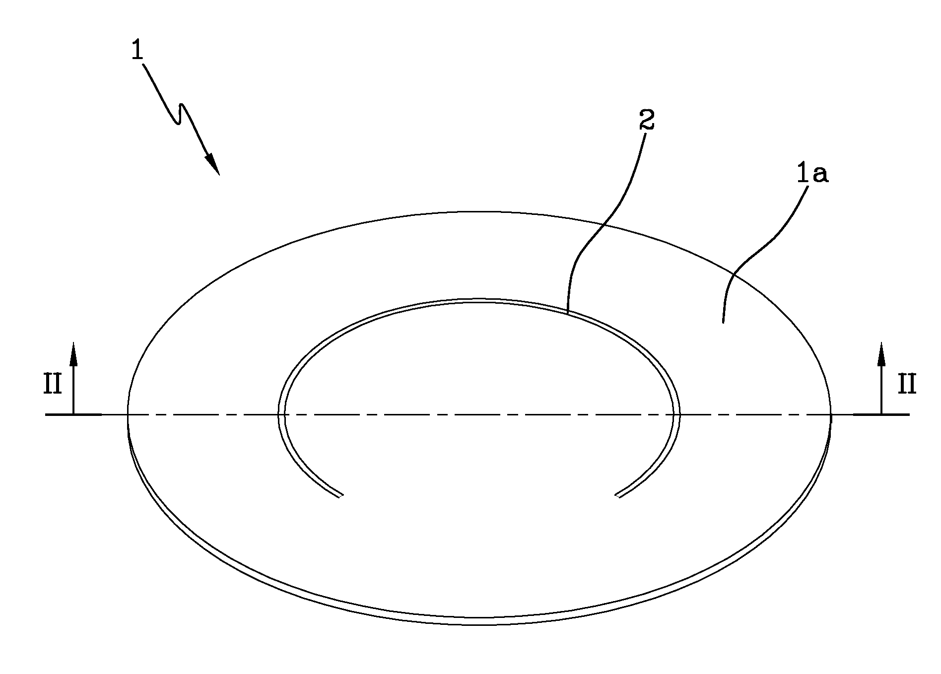
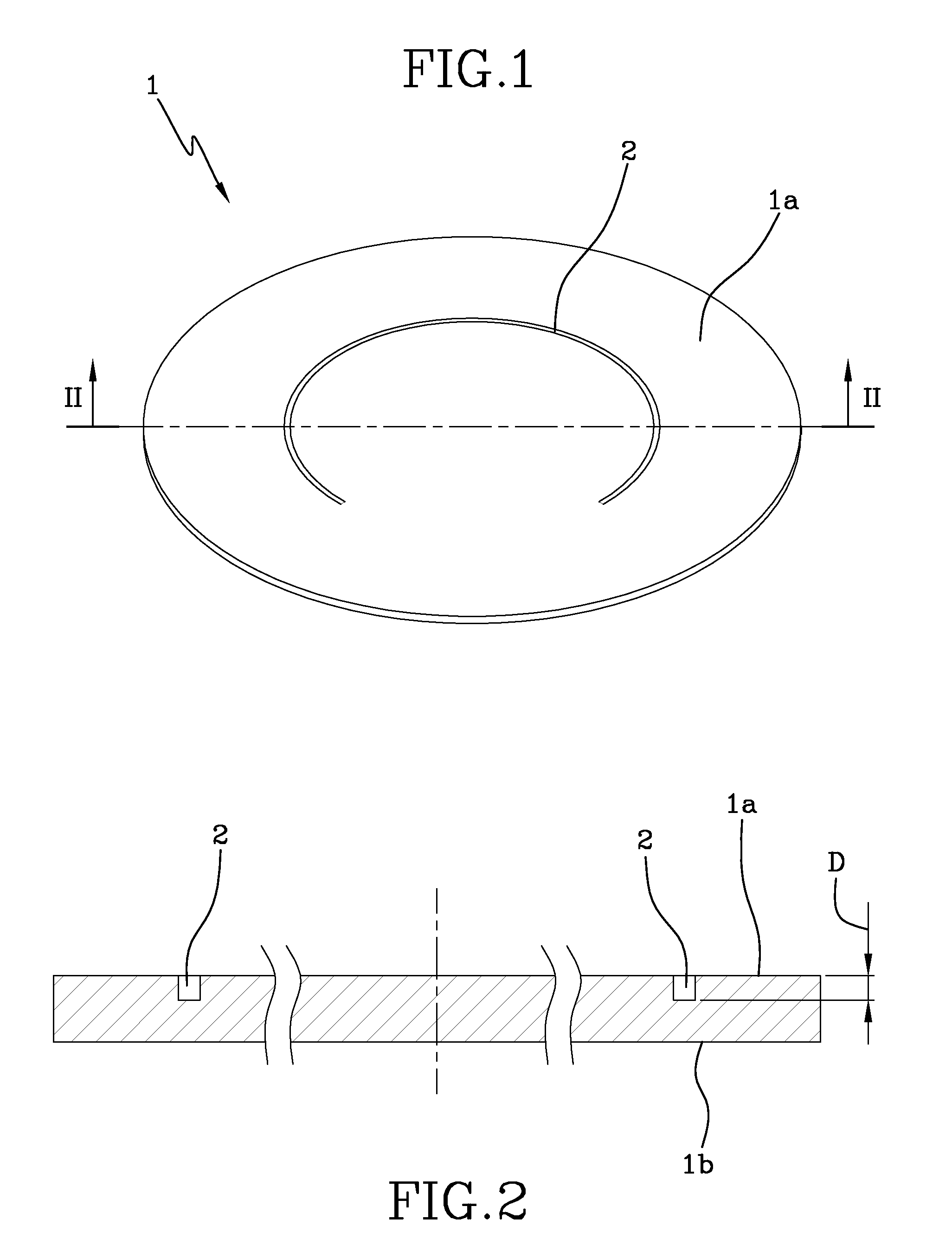
Image

Examples
example 1
The Following Values should be Intended as Indicatives, Namely as Average Values within a Range of ±10%
[0078]Material of the foil element: stainless steel AISI 316L
Thickness of the foil element: 150 μm
Wavelength of the laser: 1030 nm
Power of the laser: 20 W
Pulse duration: 6 picoseconds
Energy value of each pulse: 25 microJoule
Pulse repetition rate: 100 KHz
Speed of relative motion: 25 m / s
Passes: 3000
[0079]The average depth of non-through cuts or scores for each pass is about 0.03 μm.
[0080]The total depth of the non-through cuts is about 95 μm.
[0081]The average pressure rupture of the safety disc is 11.9 barg (difference of pressure measured in bar between the two sides of the disc) with standard deviation of 0.46.
[0082]Distance between two spots: 160 μm
example 2
The Following Values should be Intended as Indicatives, Namely as Average Values within a Range of ±10%
[0083]Material of the foil element: stainless steel AISI 316L
Thickness of the foil element: 20 μm
Wavelength of the laser: 1030 nm
Power of the laser: 20 W
Pulse duration: 6 picoseconds
Energy value of each pulse: 25 microJoule
Pulse repetition rate: 100 KHz
Speed of relative motion: 25 m / s
Passes: 250
[0084]Distance between two spots: 250 μm
[0085]The average depth of non-through cuts or scores for each pass is about 0.04 μm.
[0086]The total depth of the non-through cuts is about 10 μm. The average pressure rupture of the safety disc is 1.6 barg (difference of pressure measured in bar between the two sides of the disc) with standard deviation of 0.05.
[0087]According to another embodiment of the present invention, the method comprises the step of providing a foil element, selecting a wavelength for a laser beam of a pulse laser within a range of between 1000 nm and 1600 nm, selecting a pulse...
example 3
The Following Values should be Intended as Indicatives, Namely as Average Values within a Range of ±15%
[0094]Material of the foil element: stainless steel AISI 316L
Thickness of the foil element: 20 μm
Wavelength of the laser: 1552 nm
Power of the laser: 1.4 W
Pulse duration: 800 femtoseconds
Energy value of each pulse: 14 microJoule
Pulse repetition rate: 100 KHz
Speed of relative motion: 0.09 m / s
Passes: 6
[0095]The average depth of non-through cuts or scores for each pass is about 1.6 μm.
[0096]The total depth of the non-through cuts is about 10 μm. The average pressure rupture of the safety disc is 1.4 barg (difference of pressure measured in bar between the two sides of the disc) with standard deviation of 0.10.
[0097]Distance between two spots: 0.9 μm.
[0098]It has been noted that the resolidified layer on the bottom is less than one micron.
[0099]According to what above, the present method allows to obtain safety / rupture discs which cannot be obtained following the methods of laser machin...
PUM
| Property | Measurement | Unit |
|---|---|---|
| Time | aaaaa | aaaaa |
| Time | aaaaa | aaaaa |
| Time | aaaaa | aaaaa |
Abstract
Description
Claims
Application Information