Thermistor

a technology of thermistor and insulating plate, which is applied in the direction of resistors, thermistors, printed circuits, etc., can solve the problems of not all thermistors being glued properly, glue peeling, manual effort and time wasted in the process,

Inactive Publication Date: 2012-01-19
LIEN CHANG ELECTRONICS ENTERPRISE
View PDF0 Cites 5 Cited by
  • Summary
  • Abstract
  • Description
  • Claims
  • Application Information

AI Technical Summary

Benefits of technology

[0007]The object of the present invention is to provide a thermistor that connects to a metallic fixing piece. The fixing piece is designated for soldering onto the printed circuit board, thereby anchoring the thermistor to the printed circuit board more securely.

Problems solved by technology

Several disadvantages are associated with the above practice.
First, not all thermistor may be glued properly.
Second, the glue may peel off.
Thirdly, manual effort and time are wasted in the process.

Method used


Image

  • Thermistor
  • Thermistor
  • Thermistor

Examples


Embodiment Construction

[0017]The aforementioned illustrations and following detailed descriptions are exemplary for the purpose of further explaining the scope of the present invention. Other objectives and advantages related to the present invention will be illustrated in the subsequent descriptions and appended drawings.

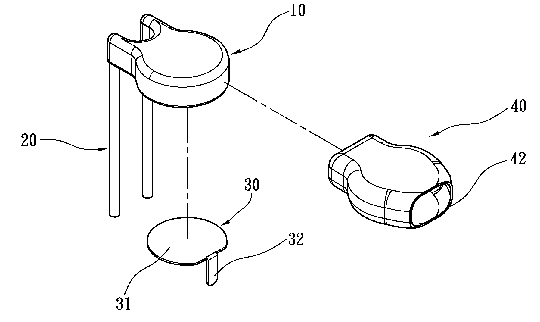
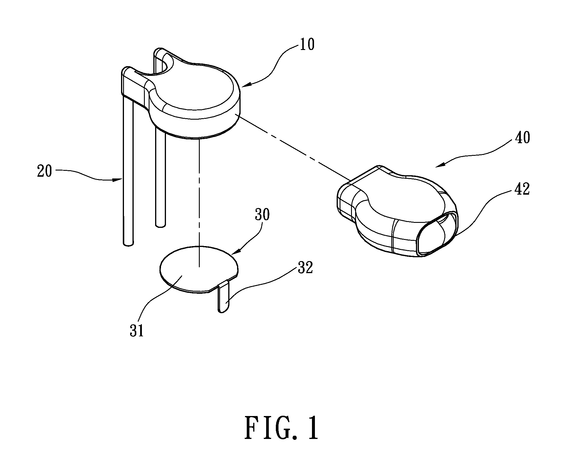
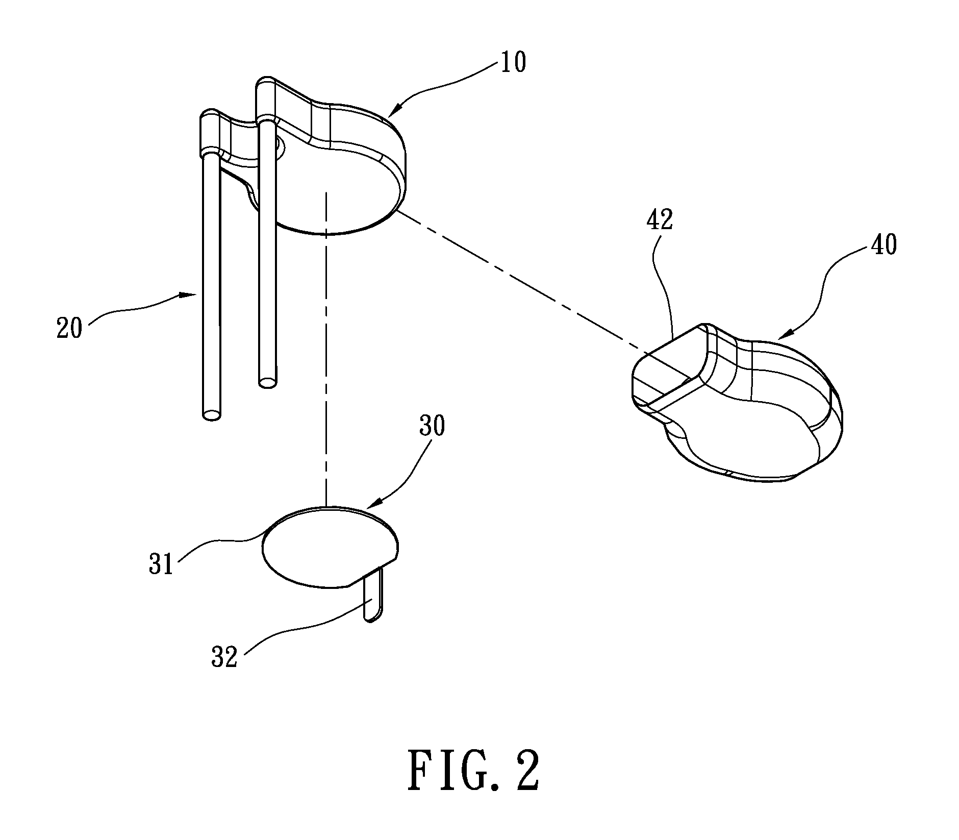
[0018]Please refer to FIG. 1-3. The present invention provides a thermistor including a main body 10, two electric plugs 20, a metallic fixing piece 30, and a cover 40.

[0019]The two electric plugs 20 are located on one end of the main body 10 and electrically connected to the main body 10. The two electric plugs 20 have different polarities from each other, with equal or different lengths. The electric plugs 20 are connected mechanically and electrically to the slots in the printed circuit board (not shown in picture).

[0020]The metallic fixing piece 30 is located on one side of the main body 10, with a connecting portion 31 and a soldering portion 32. The shape of the connecting portion ...


PUM


Abstract

A thermistor comprises a main body, two electric plugs, a metallic fixing piece, and a cover. The electric plugs are located on one end of the main body, and the metallic fixing piece is located on the side of the main body. The metallic fixing piece has a connecting portion up against one side of the main body, and a soldering portion located on the other end of the main body, opposite to the electric plugs and protruding from the main body. The cover is over the main body and the connecting portion of the metallic fixing piece, thereby securing the metallic fixing piece to the main body. The soldering portion of the metallic fixing piece can be soldered directly onto the printed circuit board, thereby anchoring the thermistor to the printed circuit board more securely.

Description

BACKGROUND OF THE INVENTION[0001]1. Field of the Invention[0002]The present invention relates to a thermistor; in particular, to a thermistor capable of being fixed to a printed circuit board firmly.[0003]2. Description of the Related Art[0004]Based on temperature change, the resistance of a thermistor changes accordingly. With high sensitivity, accuracy and stability, the thermistor is widely used as a sensor in measuring, compensating, and controls. Industrial applications include consumer electronic products, automobiles, medical instruments, food processing, communication and instrumentation, military equipments, aerospace, and research & development areas.[0005]When mounting the thermistor onto the printed circuit board, the conventional procedure involves connecting both electric plugs of the thermistor into the pre-cut slots on the circuit board. Next, the assembly is transferred to a tin soldering furnace, where the electric plugs are soldered onto the printed circuit board....

Claims


Application Information

Patent Timeline
Patent Type & Authority Applications(United States)
IPC IPC(8): H01C7/00
CPCH01C7/008
Inventor CHAN, CHUN-KONGCHEN, CHI-CHING
Owner LIEN CHANG ELECTRONICS ENTERPRISE
Why Eureka
Try Eureka