IV monitoring by video and image processing

Inactive Publication Date: 2012-01-19
TAO KAI
View PDF54 Cites 78 Cited by
  • Summary
  • Abstract
  • Description
  • Claims
  • Application Information

AI Technical Summary

Benefits of technology

[0022]For detecting the end of the dripping process we find the location of the liquid surface in the drip chamber. However, since the dripping causes agitation in the liquid surface, we compute first the average of several consecutive images

Problems solved by technology

IV dripping usually takes a long time.
When this surface be

Method used


Image

  • IV monitoring by video and image processing
  • IV monitoring by video and image processing
  • IV monitoring by video and image processing

Examples


Embodiment Construction

Introduction

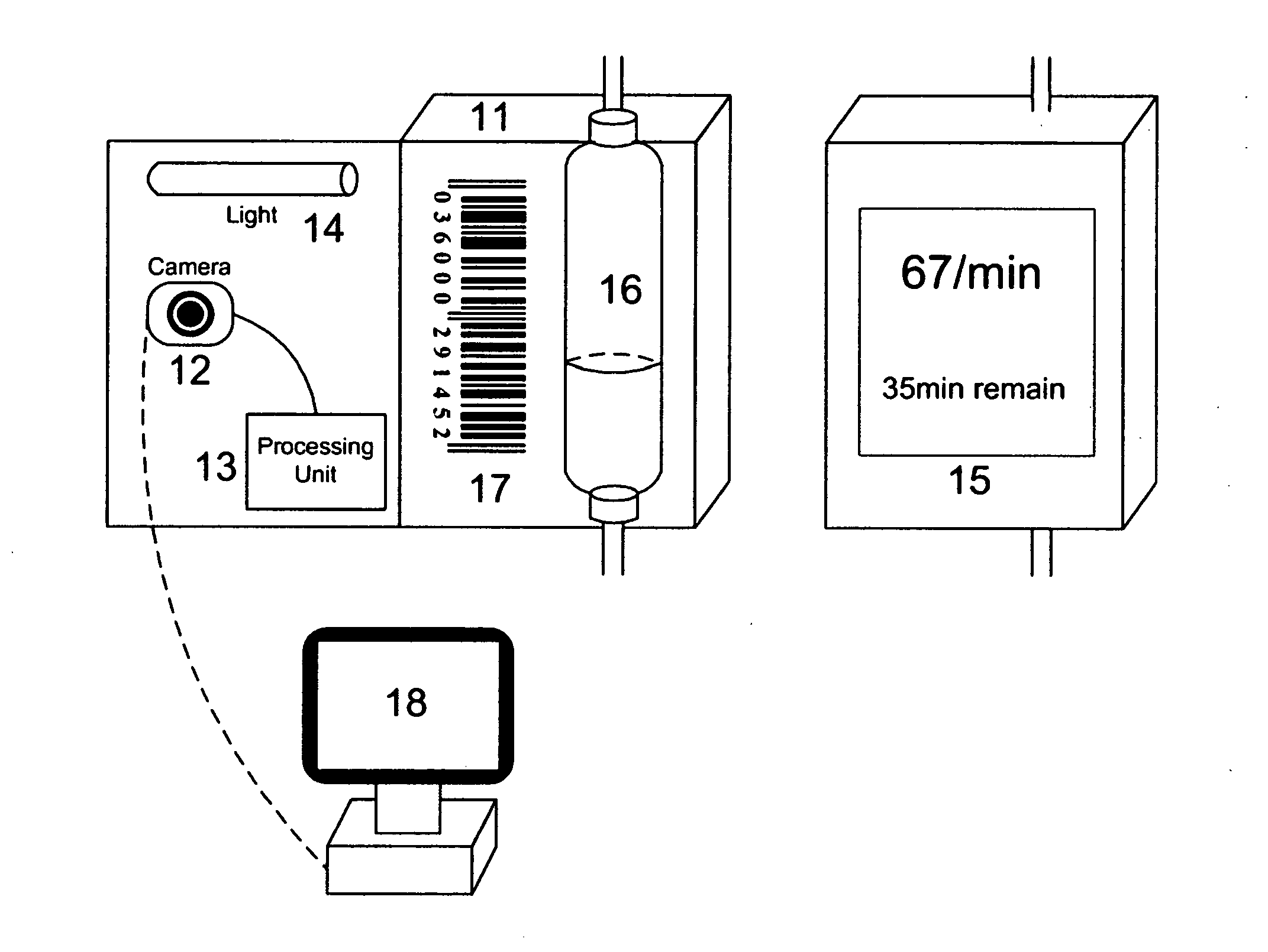
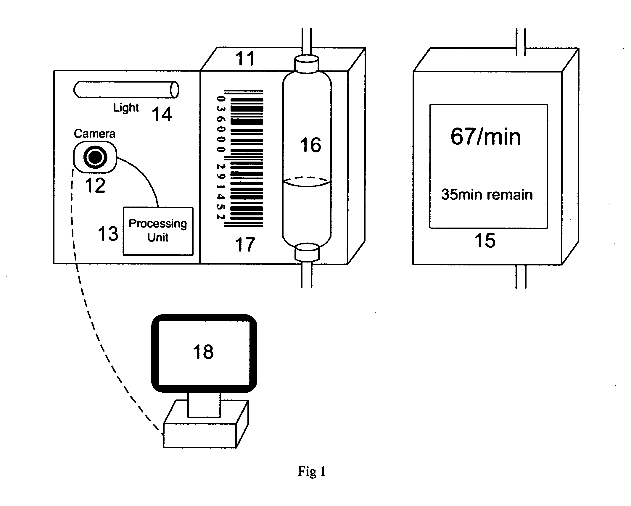
[0070]The first purpose of this invention is to ensure safety. In medical practice, there is usually requirement on the speed of N dripping. Newborns, adults, people with cardiovascular or nephropathic conditions all require different speeds. If the speed deviates too much from the prescribed value, there can be harmful effects. In the extreme cases, this can even be life-threatening.

[0071]The second purpose of this invention is to ensure efficacy. Many drugs have requirements on administration rate. If the speed is too slow or too fast, the intended effect cannot be achieved.

[0072]The third purpose of this invention is to save labor and time of nurses and patients. During the normal dripping process, both nurses and patients need to frequently check the speed and adjust it when deviation occurs and this practice occupies a large amount of their time and attention. It is also hard to estimate the remaining time for the dripping process to finish, making scheduling for nu...


PUM


Abstract

We describe a method and apparatus for monitoring the dripping speed in IV process, as well as detecting the its end. The apparatus includes a camera and a processing unit to analyze the information from the acquired video. Features from the image sequence are extracted and the dripping speed is computed accordingly by discrete Fourier transform. The apparatus is also capable of detecting the end of the dripping process by finding the location of liquid surface in the drip chamber. We also describe the use of barcode to provide information to the monitoring device and program.

Description

CROSS-REFERENCE TO RELATED APPLICATIONS[0001]Application Number 12,825,368: IV Monitoring by Digital Image Processing, by the same inventorFEDERALLY SPONSORED RESEARCH[0002]Not ApplicableTHE NAMES OF THE PARTIES TO A JOINT RESEARCH AGREEMENT[0003]Not ApplicableSEQUENCE LISTING OR PROGRAM[0004]Not ApplicableBACKGROUND[0005]1. Field of Intention[0006]This invention relates to[0007]1. IV dripping monitoring[0008]2. Use of barcode in IV monitoring[0009]2. Prior Art[0010]IV dripping usually takes a long time. Attempts have been made to automatically monitor the process and there are some existing systems. Most of them use physical approaches.[0011]One category of methods is to count the drops, and these are typically done by using optical sensors. There are several US patents falls in this category, for example:[0012]1. U.S. Pat. No. 4,383,252 Intravenous Drip Feed Monitor, which uses combination of a diode and phototransistor to detect drips.[0013]2. U.S. Pat. No. 6,736,801 Method and A...

Claims


Application Information

Patent Timeline
IPC IPC(8): H04N7/18G06K19/06
CPCH04N7/188
Inventor TAO, KAI
Owner TAO KAI
Why Eureka
Try Eureka