
Abluminally coated drug-eluting stents having a form-fitting protective layer

a technology of stents and protective layers, applied in the field of stents for implantation, can solve the problems of decreased cross-section of stents, increased muscular tension of surrounding vascular muscles, and tissue changes,

Inactive Publication Date: 2012-01-19
BIOTRONIK AG
View PDF4 Cites 8 Cited by
  • Summary
  • Abstract
  • Description
  • Claims
  • Application Information

AI Technical Summary

Benefits of technology

[0012]It is the object of the present invention to reduce or prevent at least one of the disadvantages of the prior art,

Problems solved by technology

For example, irritations and inflammations occur in a relatively short time, which can lead to tissue changes.
A key problem of stenting into blood vessels is restenosis as a result of excessive neointimal growth, for example, which is caused by a strong proliferation of the surrounding arterial smooth muscle cells and / or a chronic inflammation reaction.
For example, the decomposition of magnesium-containing stents creates an alkaline environment, which may result in increased muscular tension of the surrounding vascular muscle.
As a result of such increased muscular tension, the cross-section of the stent may decrease or the stent integrity may even be lost prematurely.
One problem of such stents having in particular only an abluminal active ingredient-releasing coating (referred to as “drug-eluting stents” or DES) is that part of the active ingredient-releasing coating is uncontrollably lost as a result of the mechanical stress that occurs during crimping and the subsequent dilation at the target site.
On the one hand, this causes the quantity of the active ingredient that is in fact available at the target site for use is very difficult to predict, thereby creating the possibility of underdosing.
On the other hand, the active ingredients that are employed are active ingredients that have significant potential for side effects, which when applied to an unintended site or released systematically in high volume may have a negative impact on the patient being treated.

Method used


Image

  • Abluminally coated drug-eluting stents having a form-fitting protective layer
  • Abluminally coated drug-eluting stents having a form-fitting protective layer
  • Abluminally coated drug-eluting stents having a form-fitting protective layer

Examples


Embodiment Construction

[0046]The invention will be explained in more detail hereinafter based on exemplary embodiments.

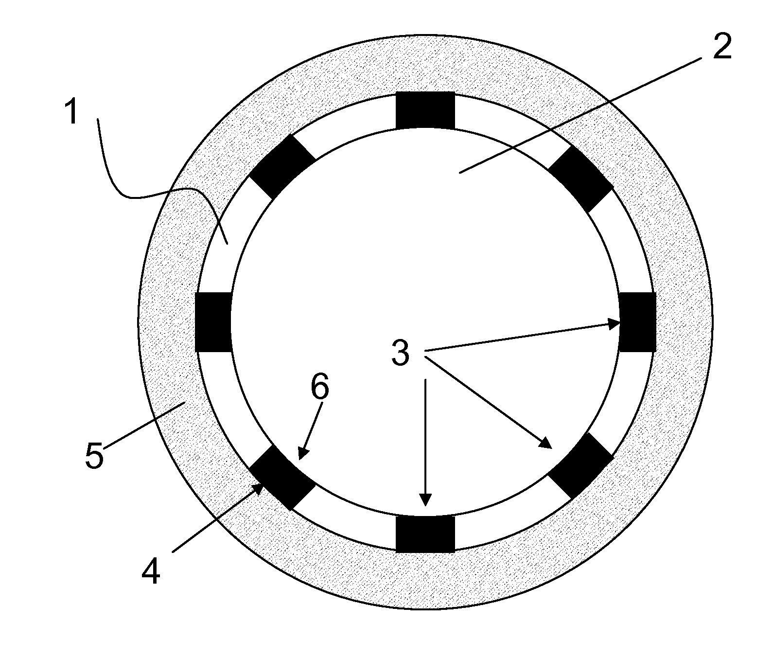
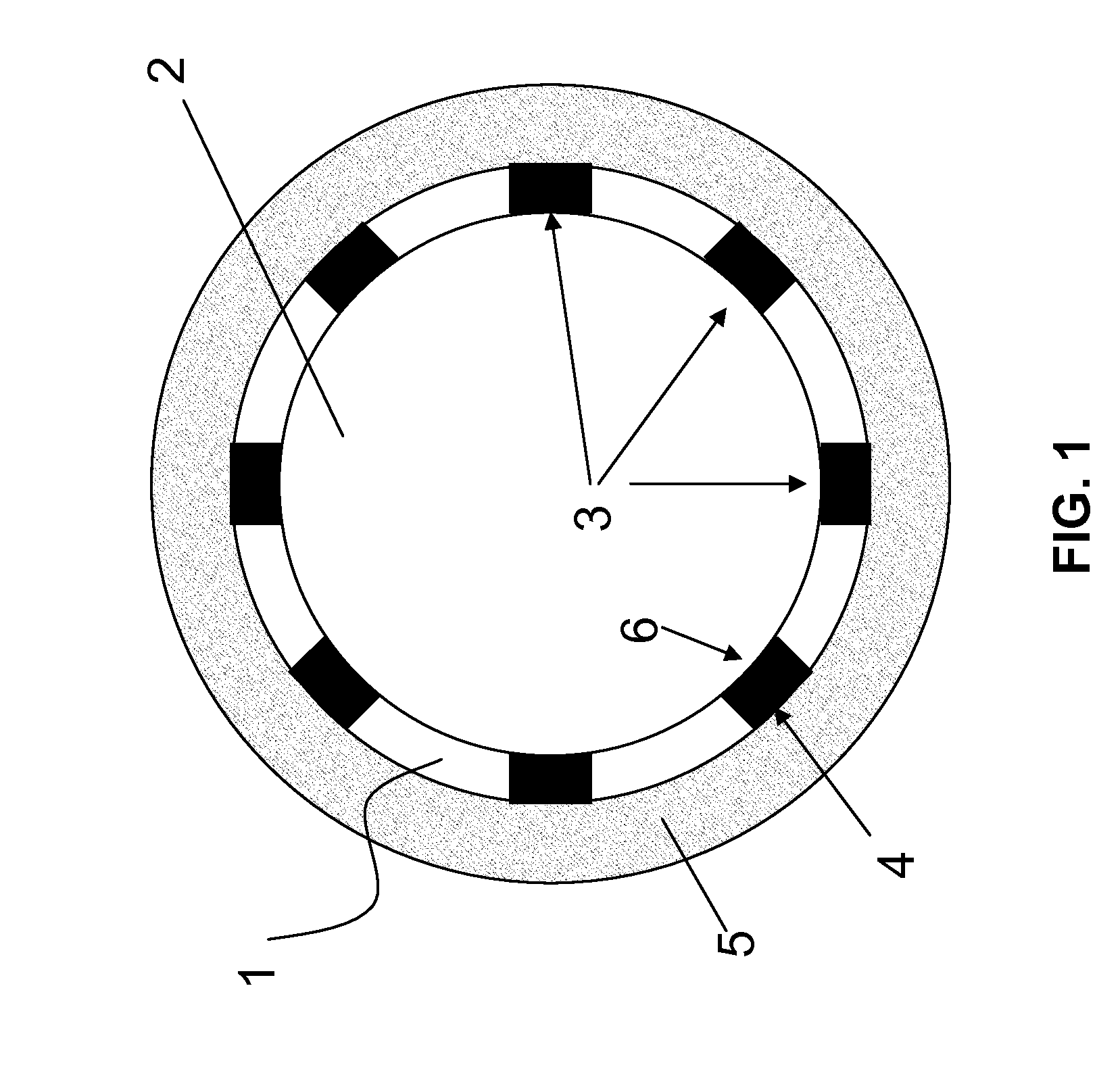
[0047]FIG. 1 is a schematic cross-section of a vessel section in which one embodiment of the stent according to the invention was implanted. The cutting plane is located perpendicular to the longitudinal axis of the stent. The stent 1 according to the invention delimits a lumen 2 and comprises struts 3, which support the vascular wall 5 with the abluminal sides 4 thereof and adjoin the lumen 2 with the luminal sides 6 thereof.

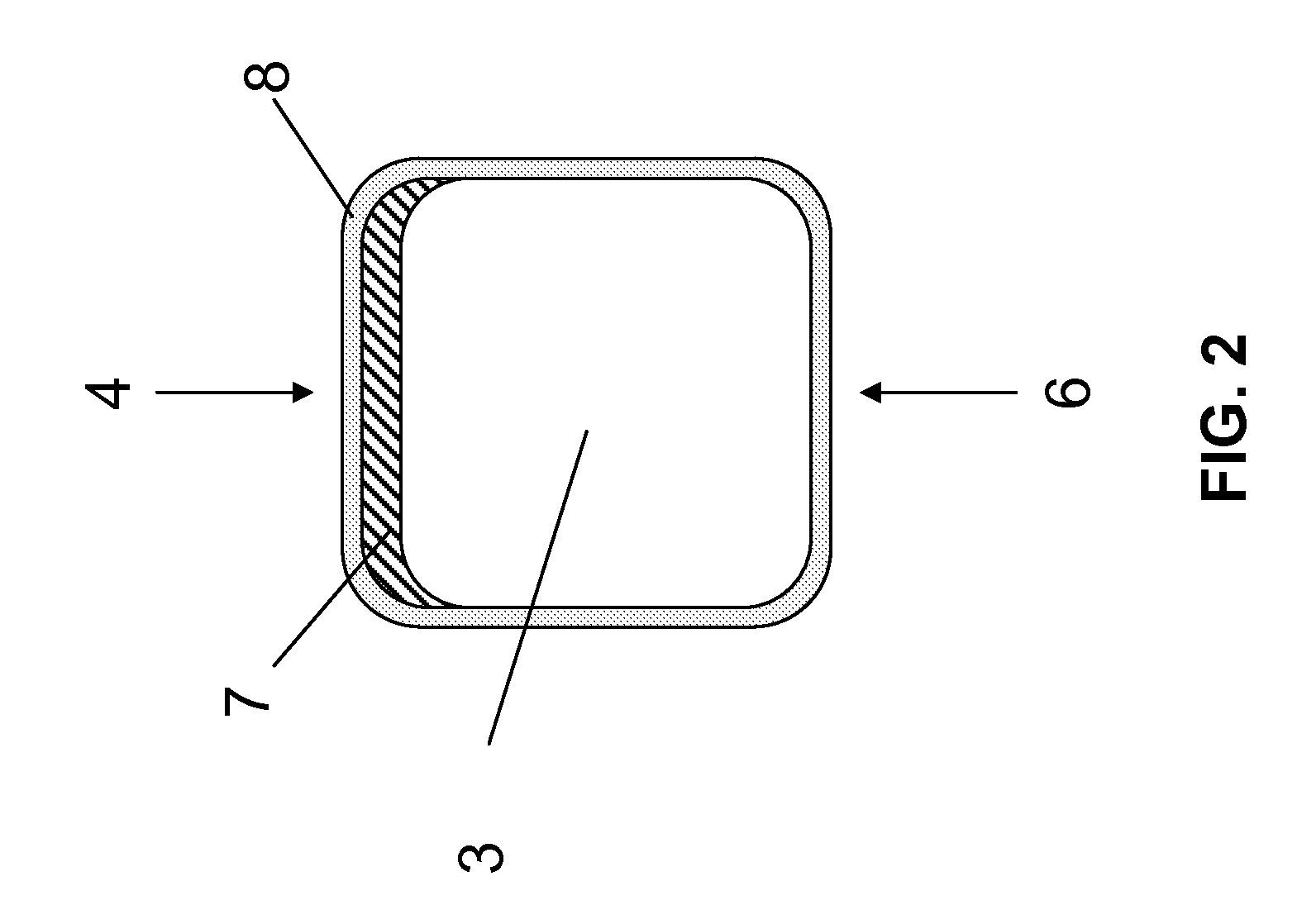
[0048]FIG. 2 shows the cross-section of a strut of a stent according to the invention. At the abluminal side 4, the strut 3 comprises an active ingredient-releasing coating 7. The strut comprises a biocorrodible protective layer 8 both on the luminal side and on the abluminal side carrying the active ingredient-releasing coating 7. The biocorrodible protective layer 8 entirely and form-fittingly covers the luminal and abluminal surfaces of the strut 3. The use of suc...


PUM

PropertyMeasurementUnit
Timeaaaaaaaaaa
Timeaaaaaaaaaa
Percent by massaaaaaaaaaa

Abstract

A drug-eluting stent, comprising a base body that is made of an implant material, the base body being partially or entirely covered on the abluminal side with an active ingredient-releasing coating that comprises or is made of a polymer and an active ingredient having an antiproliferative effect, characterized in that the stent's luminal surface and the abluminal surface carrying the active ingredient-releasing coating are covered by a biocorrodible protective layer in a form-fitting manner.

Description

CROSS REFERENCE TO RELATED APPLICATIONS[0001]This invention claims benefit of priority to U.S. patent applications Ser. No. 61 / 364,817 filed on Jul. 16, 2010; the contents of which are herein incorporated by reference in their entirety.TECHNICAL FIELD[0002]The invention relates to a stent for implantation.BACKGROUND[0003]The implantation of stents has become established as one of the most effective therapeutic measures for the treatment of vascular diseases. Stents have the purpose of performing a stabilizing function in hollow organs of a patient. For this purpose, stents featuring conventional designs have a filigree supporting structure comprising metal braces, which is initially present in a compressed (“crimped”) form for introduction into the body and is expanded at the site of the application. One of the main application areas of such stents is to permanently or temporarily dilate and hold open vascular constrictions, particularly constrictions (stenoses) of the coronary bloo...

Claims


Application Information

Patent Timeline
IPC IPC(8): A61F2/82
CPCA61L31/022A61L31/10A61L31/045A61L31/16A61L2420/08A61L31/148
Inventor KLOCKE, BJOERNHARDER, CLAUSBORCK, ALEXANDER
Owner BIOTRONIK AG
Learn More