
System and method for processing material to generate syngas

a technology of material and syngas, applied in the field of material processing, can solve the problems of municipal solid waste (msw), significant problems, and solid sludge (mss)

Active Publication Date: 2012-01-26
RESPONSIBLE ENERGY
View PDF13 Cites 3 Cited by
  • Summary
  • Abstract
  • Description
  • Claims
  • Application Information

AI Technical Summary

Benefits of technology

[0014]In an embodiment of the present invention, the material feed system comprises a material feed screw operable to move material from the material input opening towards the electrodes at a controlled rate when rotated. In some cases, a control system may be operable to manage a speed of rotation of the material feed screw based upon a monitored aspect of the gas extracted by the gas removal system. In an embodiment, the material feed screw comprises a central shaft and at least one flute connected to the central shaft. The flutes may be perforated and / or serrated. The system may further comprise a water injection system within the reactor chamber operable to inject water into the reactor chamber while electricity is applied to the electrodes. The water injection system and / or the gas removal system may be integrated with the material feed screw. In some embodiments, the system may further comprise a material injection system operable to move material into the reactor chamber. The material injection system may comprise a material injection screw operable to move material towards the material input opening when rotated. The material injection system may compress the material in order to seal the material input opening and prevent gas from escaping from the reactor chamber through the material injection system.

Problems solved by technology

Disposal of Municipal Solid Waste (MSW) and Municipal Solid Sludge (MSS) are significant issues throughout the world, and especially in the developed world.
The traditional techniques of either burying or incinerating MSW and MSS are resulting in significant problems.
Landfills are increasingly running out of space and there is becoming a large requirement to truck huge amounts of MSW / MSS to distant locations due to the public's unwillingness to have landfills in their neighborhood.
The environmental impact of dumping the MSW and MSS and / or incinerating it in a traditional fashion are enormous with toxins leaching into the soil surrounding landfills and potentially carcinogenic elements entering the air during incineration.
The problem is these solutions do not solve the underlying environmental problems and do not come close to properly capturing the energy within the MSW and MSS.
Unfortunately, thus far, there have been no municipal scale implementations of plasma arc gasification due to a number of limiting aspects of the technology.
Firstly, most implementations of the technology have not been designed to manage the high flow rate of MSW that would be required in a commercial facility.
Further, the pyrolysis techniques used have led to high levels of contaminant compounds such as tars, rather than the full conversion to hydrogen H2, carbon monoxide CO, carbon dioxide CO2 and hydrocarbons (C1 to C4s).
The inconsistent nature of the MSW input material has led to high variability in the quality of the generated syngas.
Yet further, high levels of energy are consumed in the creation of the plasma arc and, in some instances, in drying the MSW prior to processing due to moisture limits on the input materials, while the generated syngas has a low calorific value, typically less than half of the BTU content of natural gas.
These concerns have limited this technology, despite the significant benefits of converting MSW into a valuable product such as syngas.

Method used


Image

  • System and method for processing material to generate syngas
  • System and method for processing material to generate syngas
  • System and method for processing material to generate syngas

Examples


Embodiment Construction

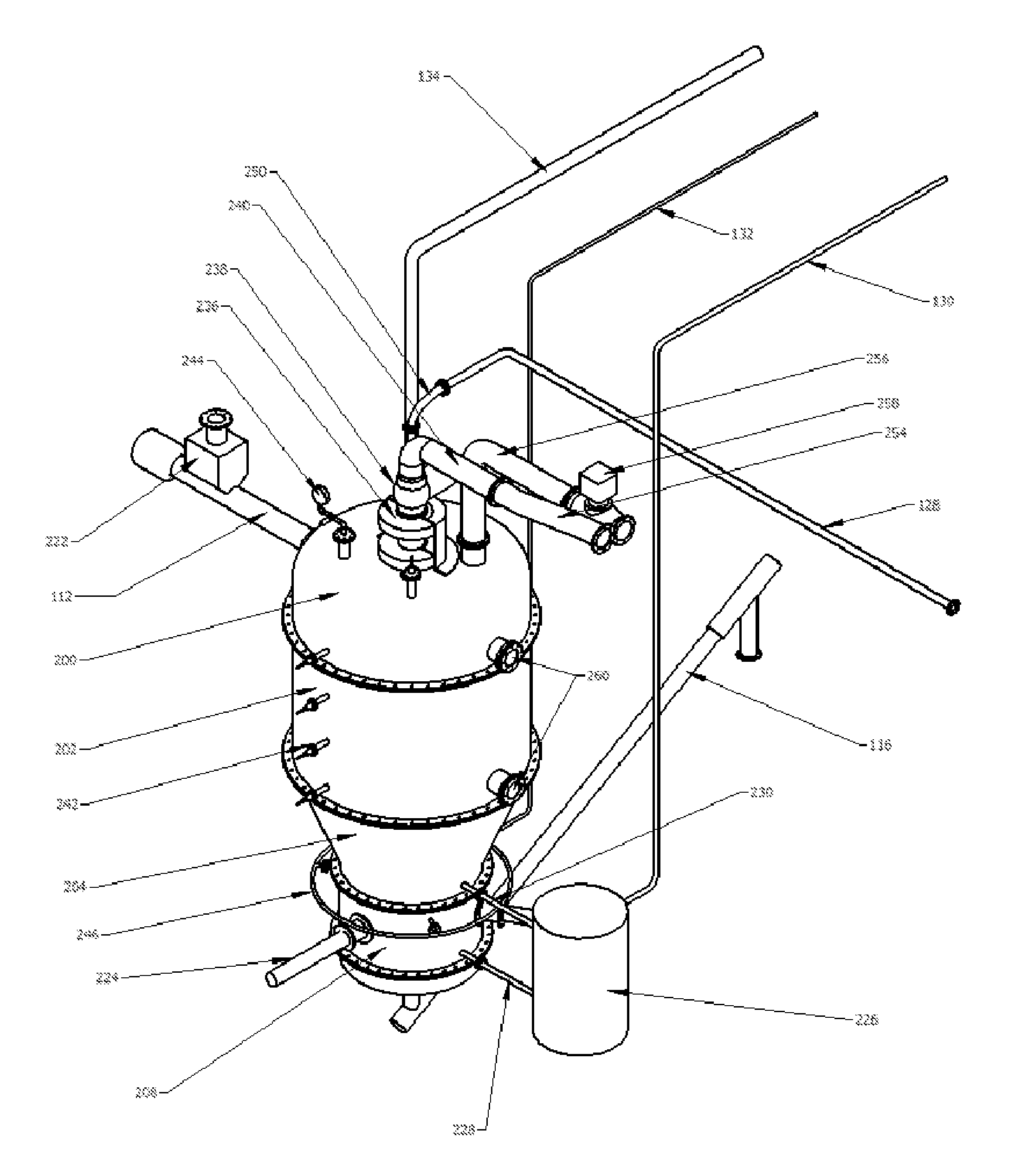
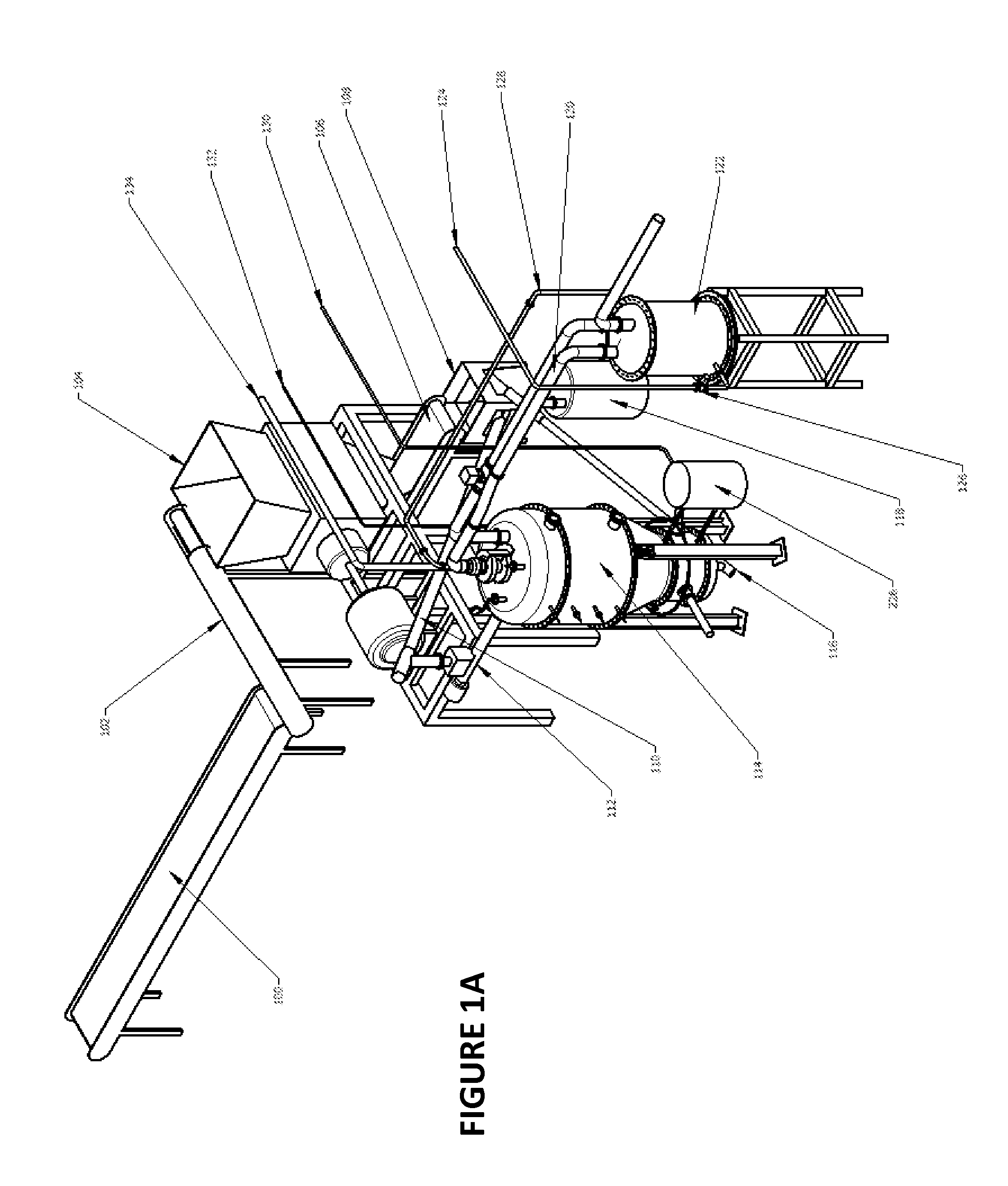
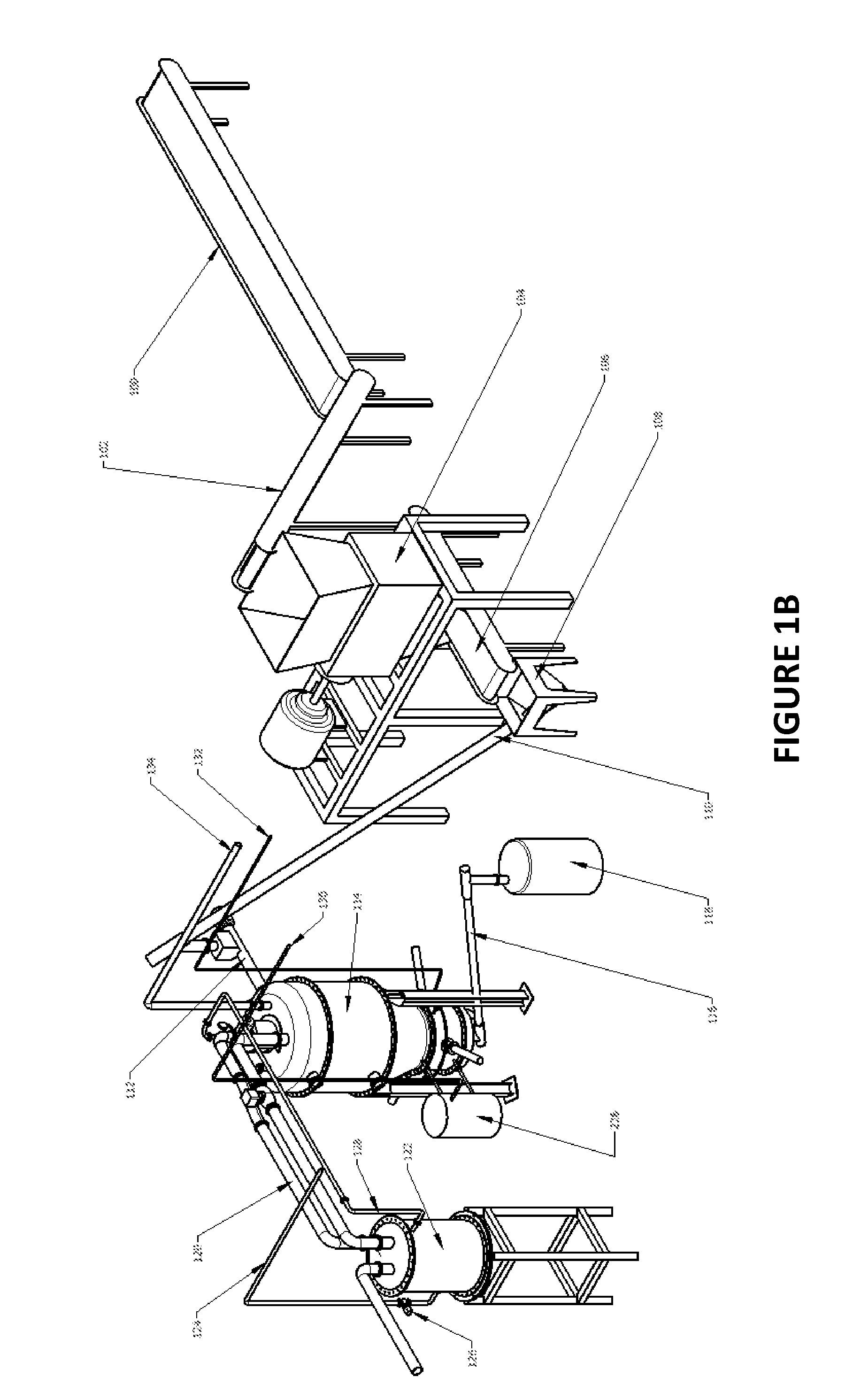
[0056]The present invention is directed to system, apparatus and method for processing material to generate syngas. As will be described herein below, the system of the present invention includes a number of different distinct mechanical elements that together allow for an efficient process flow from material input to syngas output. The system, according to some embodiments of the present invention, is designed to allow for processing of material in a controlled manner through management of various aspects of the process including, but not limited to, free radical generation, material movement rate, arc electrical power and syngas extraction locations.

[0057]The key material input needed to generate syngas is carbonaceous material (i.e. material containing carbon-based molecules). In various embodiments, the input material may be a wide range of carbonaceous materials or carbonaceous material mixed with extraneous non-carbonaceous material. In the case that it is a mixture of materia...


PUM


Abstract

The present invention is directed to system and method for processing material to generate syngas. A reactor chamber is implemented with a plurality of electrodes that can generate an arc within the chamber when electricity is applied to them. The arc can be used to create free radicals which along with the heat and light of the arc breakdown material comprising carbonaceous material, such as Municipal Solid Waste (MSW), into gas components that form syngas. The syngas can be extracted from the reactor chamber and be used for various commercial purposes. The reactor chamber may comprise a material feed system operable to move material from a material input opening in the reactor chamber towards the electrodes at a controlled rate. Further, the reactor chamber may comprise a water injection system within the reactor chamber operable to inject water into the reactor chamber while electricity is applied to the electrodes. Yet further, the reactor chamber may comprise a gas removal system within the reactor chamber operable to extract gas generated from breakdown of the material from a plurality of gas removal locations. The gas removal system may be integrated within the material feed system.

Description

CROSS-REFERENCE TO RELATED APPLICATION[0001]The present application claims the benefit under 35 U.S.C. §120, as a continuation of PCT Patent Application Serial No. PCT / CA2010 / 001663, filed on Oct. 22, 2010 entitled “SYSTEM AND METHOD FOR PROCESSING MATERIAL TO GENERATE SYNGAS” by Robert JENSEN et al., hereby incorporated by reference herein, which in turn claims priority to U.S. Provisional Patent Application Ser. No. 61 / 366,327, filed on Jul. 21, 2010 by Robert JENSEN et al.FIELD OF THE INVENTION[0002]The invention relates generally to material processing and, more particularly, to system and method for processing material to generate syngas.BACKGROUND[0003]Disposal of Municipal Solid Waste (MSW) and Municipal Solid Sludge (MSS) are significant issues throughout the world, and especially in the developed world. The traditional techniques of either burying or incinerating MSW and MSS are resulting in significant problems. Landfills are increasingly running out of space and there is ...

Claims


Application Information

Patent Timeline
Patent Type & Authority Applications(United States)
IPC IPC(8): H05H1/48
CPCC10J2200/12C10J3/18C10J2200/158C10J3/30C10J2300/1238C10J3/726C10K1/04C10J2300/0906C10J2300/0973C10J3/32
Inventor JENSEN, ROBERT CHRISTIANHOUZE, GRAHAM CAMPBELL
Owner RESPONSIBLE ENERGY
Learn More