Three level power converting device

a three-level inverter or converter technology, applied in the direction of power conversion systems, pulse techniques, electronic switching, etc., can solve the problems of increased size, increased device price, and inability to protect, so as to suppress the surge voltage, reduce the inductance of wires, and ensure the effect of protection

Inactive Publication Date: 2012-01-26
FUJI ELECTRIC CO LTD
View PDF6 Cites 25 Cited by
  • Summary
  • Abstract
  • Description
  • Claims
  • Application Information

AI Technical Summary

Benefits of technology

[0034]As a result, wiring inductance decreases, it is possible to suppress the surge voltage when switching, and it is possible to realize a reliable protection function.

Problems solved by technology

Although protection is possible by the fuse F3 melting both when there is a failure of a semiconductor element short circuiting the upper side power supply C1 and when there is a failure of a semiconductor element short circuiting the lower side power supply C2, protection is not possible in a case of a short circuit failure occurring at a time of a two-level action using a switching of the T1 and T2.
In general, by a main circuit conductor of a direct current portion being of a parallel flat plate structure (a laminated structure), any magnetic field generated is cancelled out, and a reduction in wiring inductance is achieved, but when connecting a fuse as in the system of FIG. 6, a parallel flat plate structure cannot be adopted in that place, and it is not possible to achieve a reduction in wiring inductance.
When connecting a fuse as heretofore described, a high surge voltage is generated when switching due to an increase in inductance, the application of a module with a high withstand voltage, the connection of a snubber circuit, or the like, is necessary, and problems occur in that there is an increase in size and a rise in price of the device.
In the case of a three-level inverter in particular, as it is necessary to connect fuses in two places, these problems are notable.
Also, in the circuit configuration shown in FIG. 16, protection is not possible for a two-level action.

Method used


Image

  • Three level power converting device
  • Three level power converting device
  • Three level power converting device

Examples


working example 1

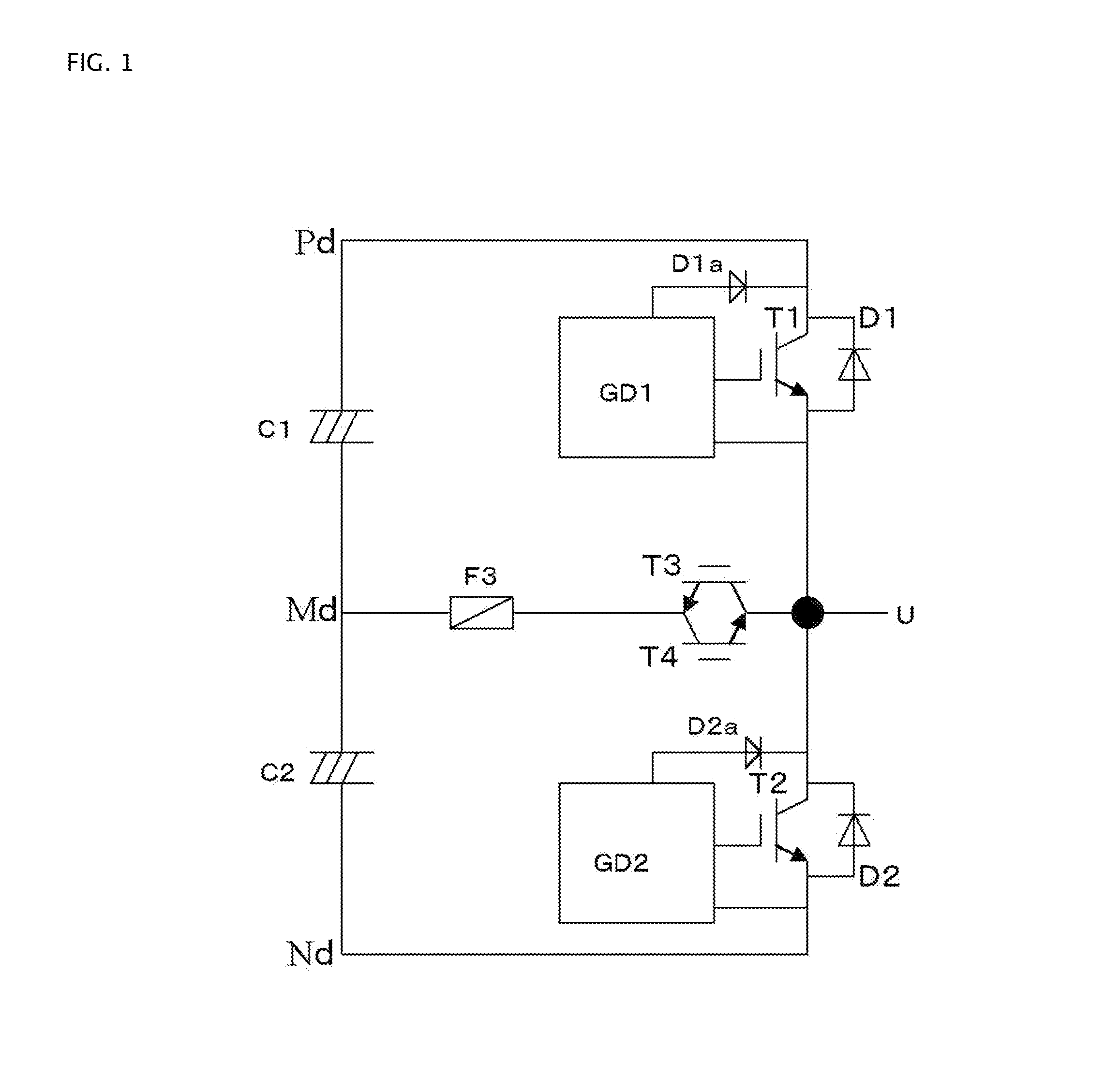
[0052]A first working example of embodiments of the invention is shown in FIG. 1. It is a circuit configuration of a voltage type three-level power converter that has, as one phase, a direct current power supply, configured with two capacitors C1 and C2 connected in series as a direct current power supply and having a positive electrode, an intermediate electrode, and a negative electrode, a first IGBT T1 whose collector is connected to the positive electrode of the direct current circuit and to which a diode D1 is connected in inverse parallel, a second IGBT T2 whose emitter is connected to the negative electrode of the direct current circuit and to which a diode D2 is connected in inverse parallel, and a bidirectional switching element configured of a third IGBT T3 and fourth IGBT T4, connected in inverse parallel, connected to the connection point of the emitter of the first IGBT T1 and collector of the second IGBT T2 and the intermediate electrode of the direct current power sup...

working example 2

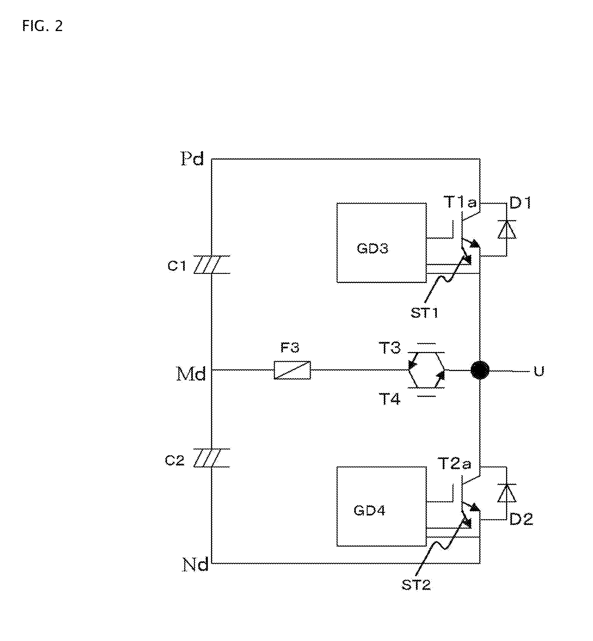
[0056]FIG. 2 shows a second working example of embodiments of the invention. The difference from the first working example is in the point that IGBTs with a current sense terminal for detecting current are used as IGBTs T1a and T2a, and the overcurrent shutdown unit detects an overcurrent with the current sense terminal, and shuts off the gate signal. As this overcurrent protection method is heretofore known from JP-A-4-79758, and the like, a detailed description will be omitted. With this kind of configuration too, in the same way as in the first working example, it is possible to realize protection of each overcurrent path.

working example 3

[0057]FIG. 3 shows a third working example of embodiments of the invention. The difference from the first and second working examples is in the point that current detectors CS1 and CS2, such as a hole CT, are used for overcurrent detection. When an overcurrent is detected, the on signal of the gate drive circuit is shut off. With this kind of configuration too, in the same way as in the first and second working examples, it is possible to realize protection of each overcurrent path.


PUM


Abstract

Aspects of the invention are directed to a three-level power converter that has, as one phase, a bidirectional switching element connected to the series connection point of a series circuit of a first insulated gate bi-polar transistor (“IGBT”) and second IGBT and an intermediate electrode of a direct current power supply. Also included is a fuse connected between the bidirectional switching element and the intermediate electrode of the direct current power supply, and an overcurrent shutdown unit provided in each gate drive circuit of the first and second IGBTs, are provided as protection from a power supply short circuit phenomenon occurring in the event of a short circuit failure of any of the IGBTs or diodes.

Description

BACKGROUND OF THE INVENTION[0001]1. Technical Field[0002]Embodiments of the present invention relate to an arm short circuit protection method of a three-level inverter or converter.[0003]2. Related Art[0004]A protection circuit wherein a fuse is used in a three-level converter is shown in Japanese Patent Publication No. JP-A-2004-248479 (see FIGS. 1 to 3). The three-level converter circuit shown here is a configuration that has, as one phase, a circuit wherein capacitors acting as a direct current power supply are connected in series, a positive electrode, an intermediate electrode, and a negative electrode act as direct current terminals, a series connection circuit of four IGBTs (two in an upper arm and two in a lower arm) to which diodes are connected in inverse parallel is connected between the positive electrode and negative electrode, and a diode for clamping the intermediate electrode is connected between the series connection point of the two upper arm insulated gate bipola...

Claims


Application Information

Patent Timeline
Patent Type & Authority Applications(United States)
IPC IPC(8): H01L29/739
CPCH02M1/32H03K17/0828H03K17/08148H02M7/483H02M7/487
Inventor TAKIZAWA, SATOKI
Owner FUJI ELECTRIC CO LTD
Why Eureka
Try Eureka