

Method and system for rail vehicle power distribution and management
a technology for rail vehicles and power distribution, applied in the direction of electric devices, transportation and packaging, constant-current supply dc circuits, etc., can solve problems such as data loss and/or corruption, battery dissipation, and battery state too low to facilitate engine starting, so as to prevent battery dissipation
- Summary
- Abstract
- Description
- Claims
- Application Information
AI Technical Summary
Benefits of technology
Problems solved by technology
Method used
Image

Examples
Embodiment Construction
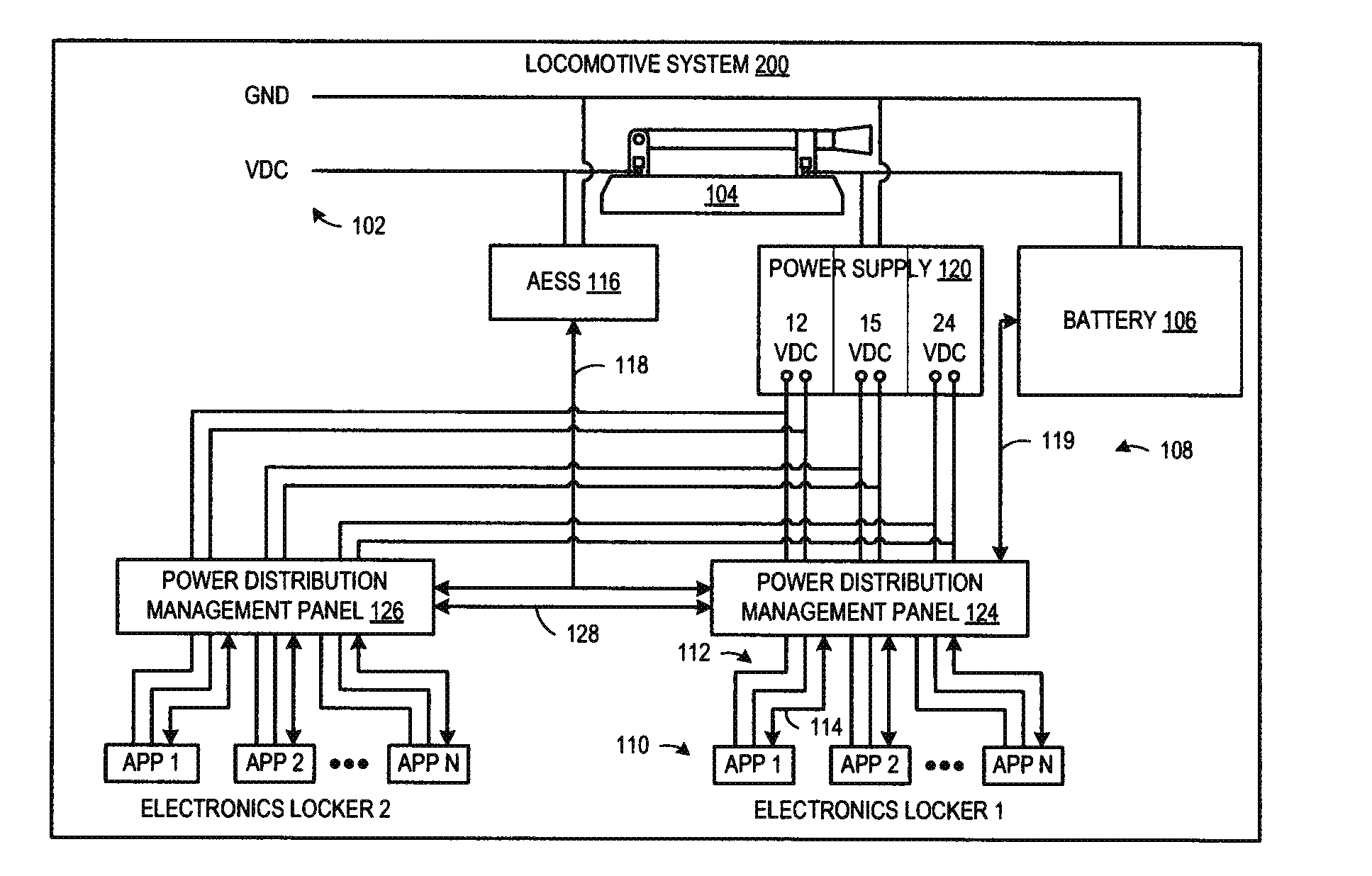
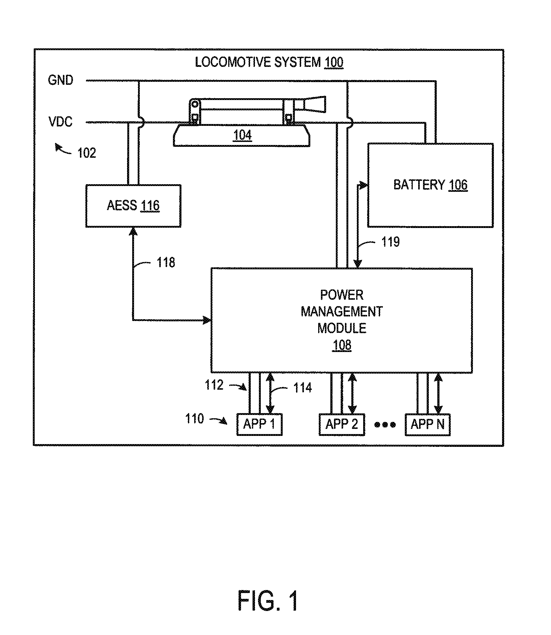
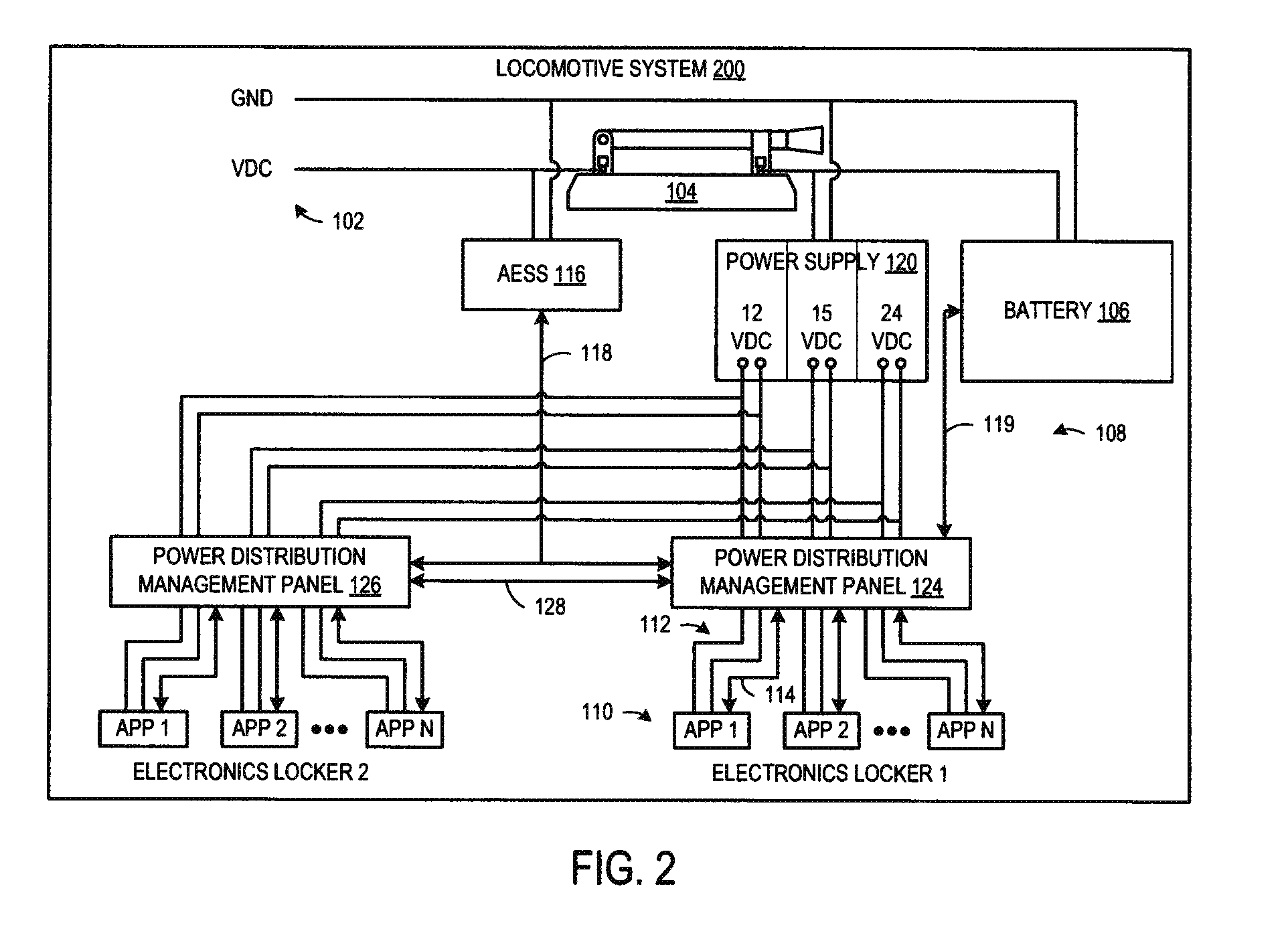
[0017]The present description relates to locomotives, or other rail vehicles, that include integrated systems for managing power distribution to various locomotive (or other rail vehicle) electronic applications and / or appliances. The power distribution management systems and methods described herein provide the ability to selectively shut-off applications and / or appliances in a predefined manner to shed power load. For example, the power distribution management systems perform power load shedding operations during standby conditions where a locomotive engine is shut-off by targeting applications and / or appliances connected on a battery-side of the knife switch that generate a power load on the battery that causes a state of charge of the battery to decrease. The power load shedding operations are performed in order to preserve battery power. The power distribution management systems allow for applications and / or appliances on the battery-side of the knife switch to remain on even a...
PUM
 Abstract
Description
Claims
Application Information