Receiver

a receiver and radio wave technology, applied in the field of receivers, can solve the problems of difficult to dispose the second antenna element on the receiver, the technology cannot be directly applied to the receiver simultaneously using a plurality of antennas, and the arrangement of the antenna elements can be difficult depending on the situation, so as to achieve the effect of reducing the additional work of securing the conductive route and advantageous antenna gain

Inactive Publication Date: 2012-01-26
PANASONIC CORP
View PDF6 Cites 3 Cited by
  • Summary
  • Abstract
  • Description
  • Claims
  • Application Information

AI Technical Summary

Benefits of technology

[0010]Thus, by disposing the partition for electrically interconnecting the parts of the case between the first through hole and the second through hole, a conductive route of image current for power supply to the first antenna and the second antenna is secured. As a result, antenna gain is improved advantageously. By securing the conductive route simultaneously with production of the case, additional work for securing the conductive route can be reduced.

Problems solved by technology

Therefore, this technology cannot be directly applied to a receiver simultaneously using a plurality of antennas, disadvantageously.
Therefore, it can be difficult to dispose the second antenna element on the receiver.
The arrangement of the antenna elements can be difficult depending on the structure of the case.

Method used


Image

  • Receiver
  • Receiver
  • Receiver

Examples


first exemplary embodiment

[0044]In the present invention, a receiver for receiving terrestrial television broadcasting with a plurality of antennas is described as an example.

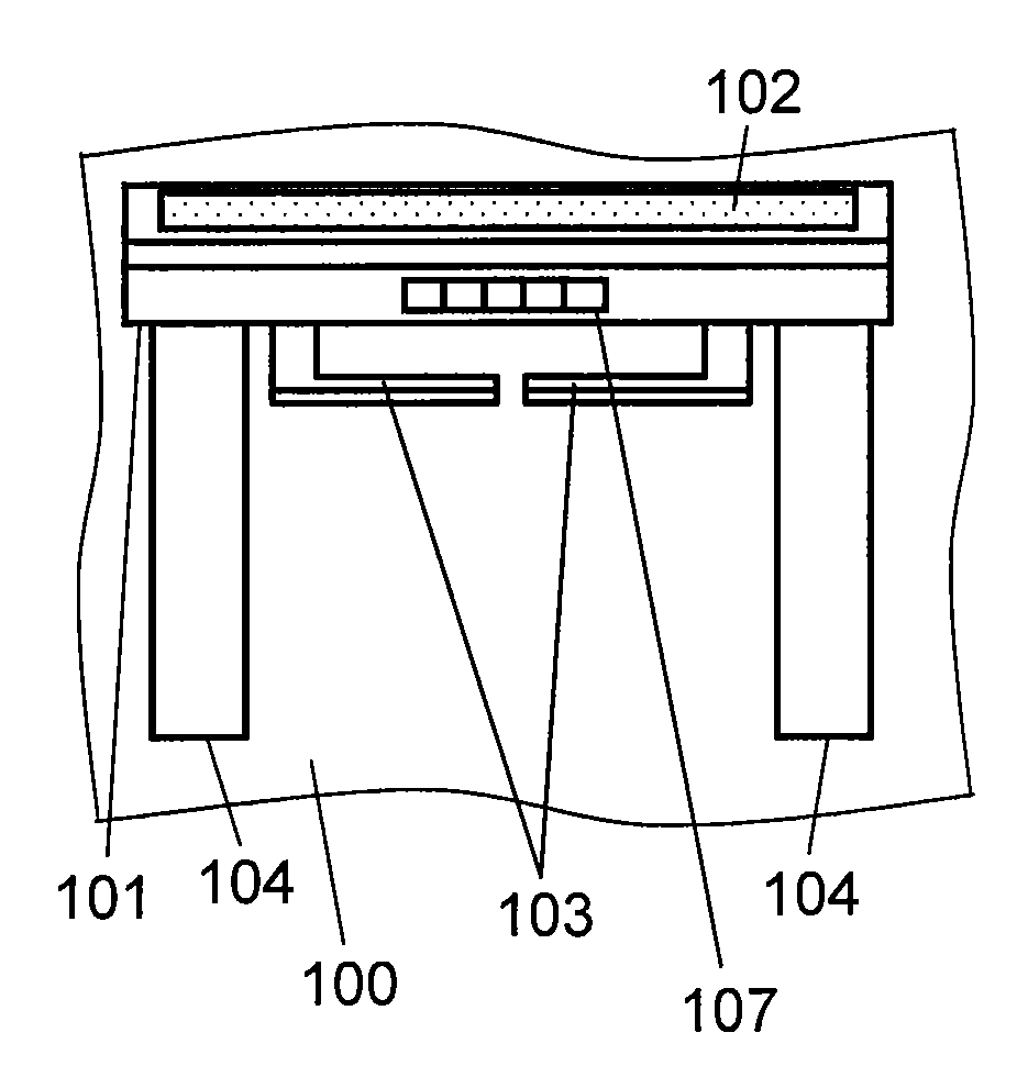
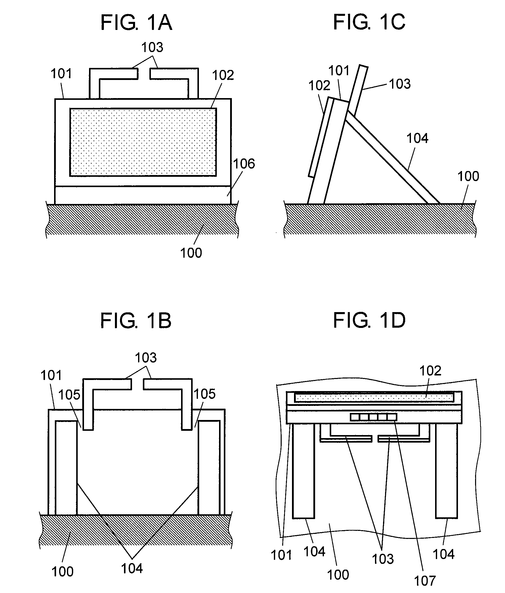
[0045]A receiver in accordance with a first exemplary embodiment of the present invention will be described hereinafter with reference to the accompanying drawings. FIG. 1A, FIG. 1B, FIG. 1C, and FIG. 1D are block diagrams showing the using state of the receiver in accordance with a first exemplary embodiment of the present invention. FIG. 1A is a front view of the receiver in a using state. FIG. 1B is a rear view of the receiver in the using state. FIG. 1C is a side view of the receiver in the using state. FIG. 1D is a top view of the receiver in the using state. The receiver is mounted on installing surface 100. The receiver includes the following elements:[0046]conductive case 101 having a built-in receiving section for receiving radio wave of terrestrial television broadcasting signals and for performing channel selection, demodulat...

second exemplary embodiment

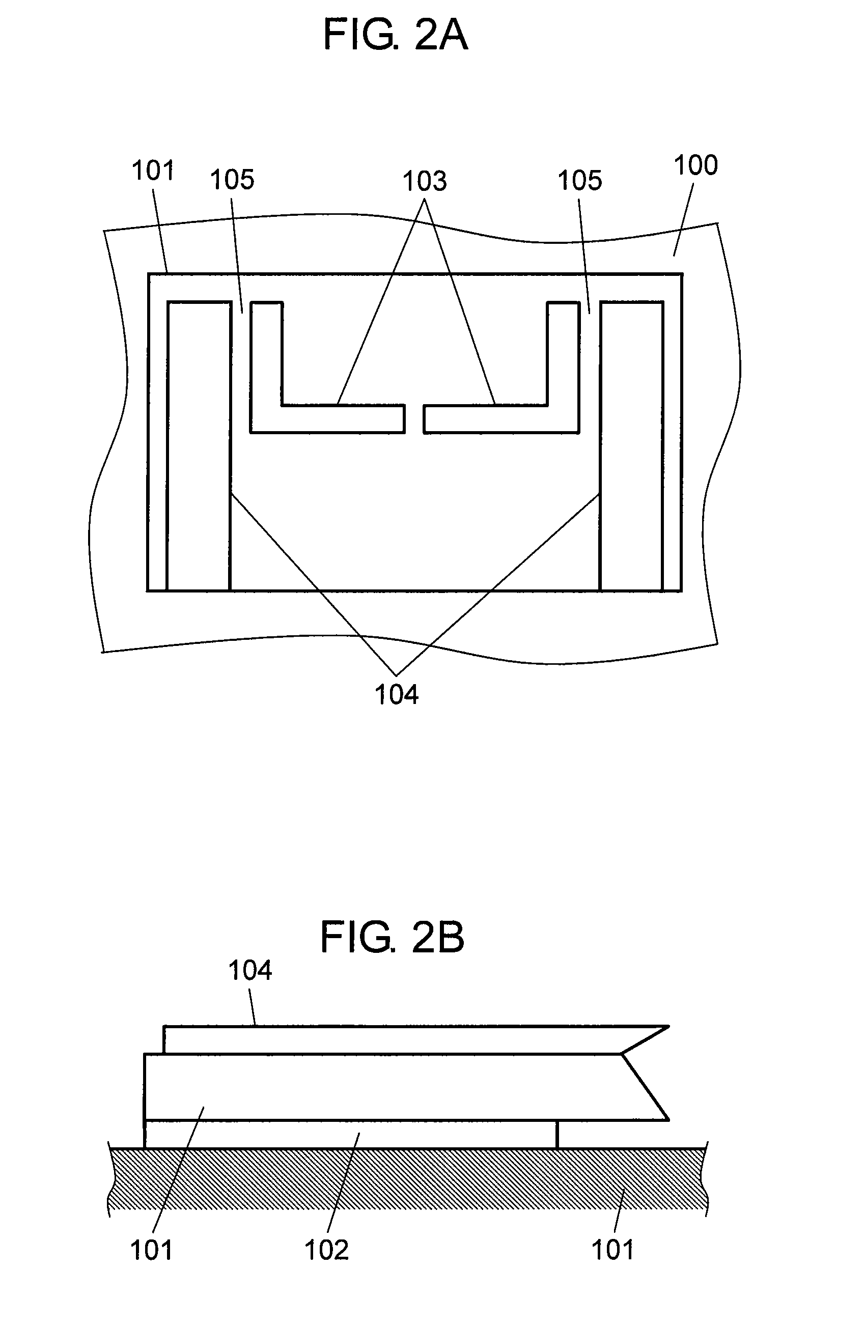
[0076]A receiver in accordance with a second exemplary embodiment of the present invention will be described hereinafter with reference to the accompanying drawings. The receiver of the second exemplary embodiment has a structure that is partially common with that of the first exemplary embodiment, so that only the different structure is described. FIG. 7A and FIG. 7B are block diagrams showing the proximity of connecting point 105 of the receiver of the second exemplary embodiment of the present invention. FIG. 7A is a schematic diagram of a surface of case 101 seen from the outside of case 101 near the connecting point in a storing state. FIG. 7B is a schematic diagram of the surface of case 101 seen from the outside of case 101 near the connecting point in a using state. Through hole 701 is a common through hole formed by connecting first through hole 405 to second through hole 406 by eliminating partition 411 of the first exemplary embodiment. Therefore, the processing property ...


PUM


Abstract

The receiver diversity-receives radio wave with a plurality of antennas. The receiver includes a conductive case having a receiving section for executing diversity-receiving processing, a first through hole and a second through hole that are disposed on the surface of the same side of the case and penetrate the case from the outside to the inside, a first antenna and a second antenna for supplying a received signal to the receiving section, and a first hinge and a second hinge that are fixed to the inside of the case, pass the first through hole and the second through hole, directly or indirectly support the first antenna and the second antenna, and are movable, respectively. A partition is disposed between the first through hole and the second through hole.

Description

[0001]THIS APPLICATION IS A U.S. NATIONAL PHASE APPLICATION OF PCT INTERNATIONAL APPLICATION PCT / JP2009 / 006574.TECHNICAL FIELD[0002]The present invention relates to a receiver for receiving radio wave for transmitting information with a plurality of antennas, and especially to a receiver for receiving terrestrial television broadcasting with a plurality of antennas.BACKGROUND ART[0003]In a conventional receiver, a first antenna element is disposed on one surface of a case, and a second antenna element is disposed on the other surface. The first antenna element and the second antenna element are fixed to a rotation shaft and unitized. The rotation shaft penetrates the case from the front surface to the rear surface, and the first antenna element and the second antenna element support the case (for example, Patent literature 1 (FIG. 8)).[0004]However, the technology disclosed in Patent literature 1 is related to a receiver that can use one of two different types of antenna elements: a...

Claims


Application Information

Patent Timeline
Patent Type & Authority Applications(United States)
IPC IPC(8): H01Q1/24H04L27/00H04N5/44
CPCH01Q1/2258H01Q9/42H04B7/08H04B1/08H01Q21/28
Inventor SUZUKI, KAZUAKIKINOSHITA, KEISUKE
Owner PANASONIC CORP
Why Eureka
Try Eureka