
System and Method for Visualizing Objects

a visualization system and object technology, applied in the field of eye surgery, can solve problems such as blurring and distortion, affecting central vision, and microscopic damage to the inner surface of the object, and achieve the effect of high accuracy

Active Publication Date: 2012-01-26
CARL ZEISS MEDITEC AG
View PDF1 Cites 18 Cited by
  • Summary
  • Abstract
  • Description
  • Claims
  • Application Information

AI Technical Summary

Benefits of technology

[0005]A common surgical technique for treatment of epiretinal membranes is vitreoretinal surgery. The surgery starts with a procedure known as vitrectomy, wherein the vitreous jell is removed from the center of the eye. Thereby, any vitreous attachment is removed from the central macular region. Then, specialized microsurgical instruments are used to gently peel and remove the scar tissue from the surface of the retina, relieving the traction and reducing the distortion to the retinal surface.
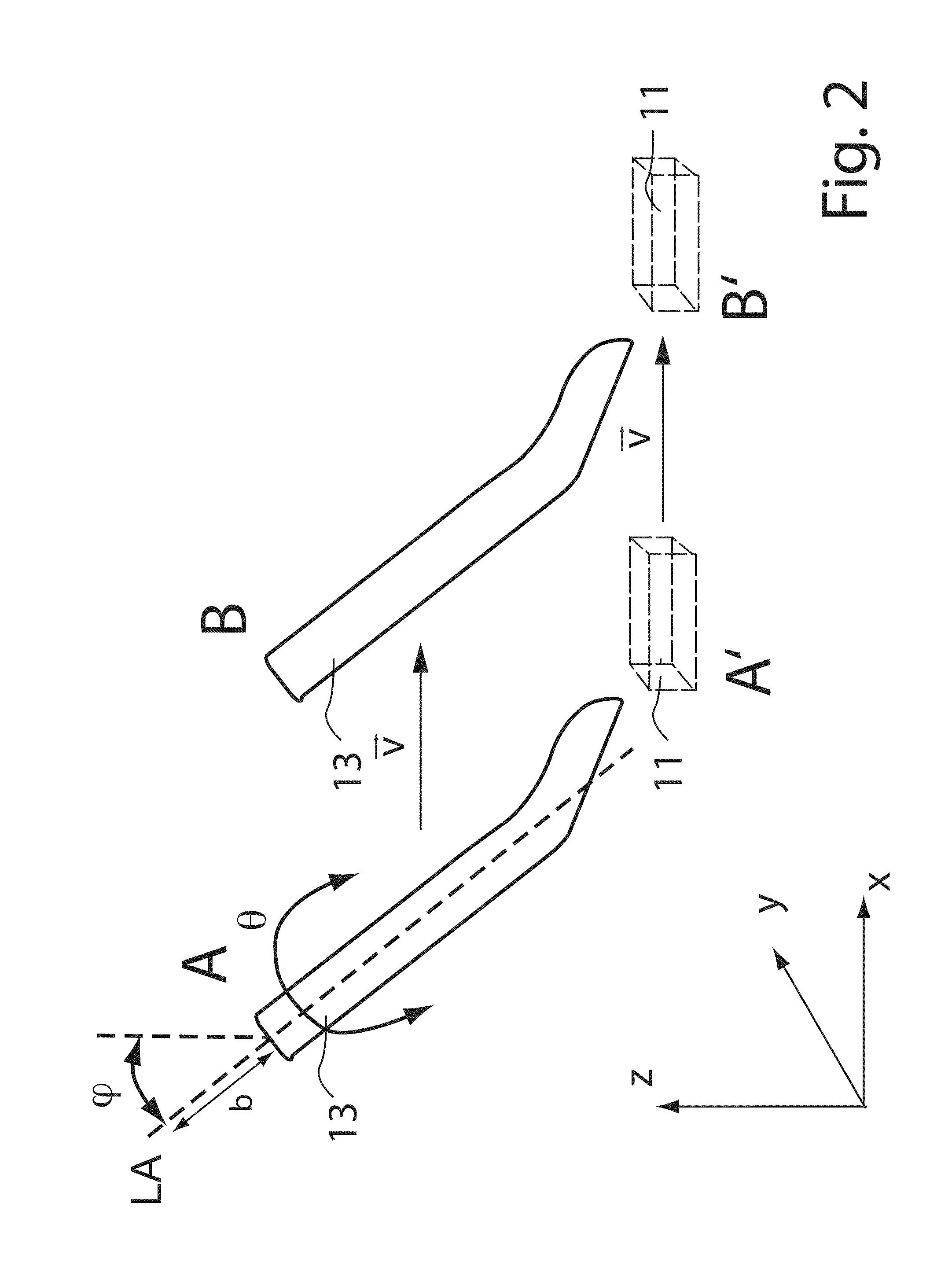
[0094]Accordingly, it is possible to obtain position data indicative of a position of a predetermined portion of the movable instrument with a high accuracy.

Problems solved by technology

Shrinkage and forward movement of the vitreous may cause traction or pulling on the retina, which can result in microscopic damages to its inner surface.
It typically progresses slowly and affects central vision by causing blurring and distortion.
In the eyes of some patients, the layer of the epiretinal membrane on the surface of the macula results in mechanical wrinkling and distortion of the retina, which may lead to decreased vision.
Also, it is difficult for the surgeon to determine the best edge of the epiretinal membrane for continuing the peeling process.
However, said dyes raised questions with regards to their safety.

Method used


Image

  • System and Method for Visualizing Objects
  • System and Method for Visualizing Objects
  • System and Method for Visualizing Objects

Examples


Embodiment Construction

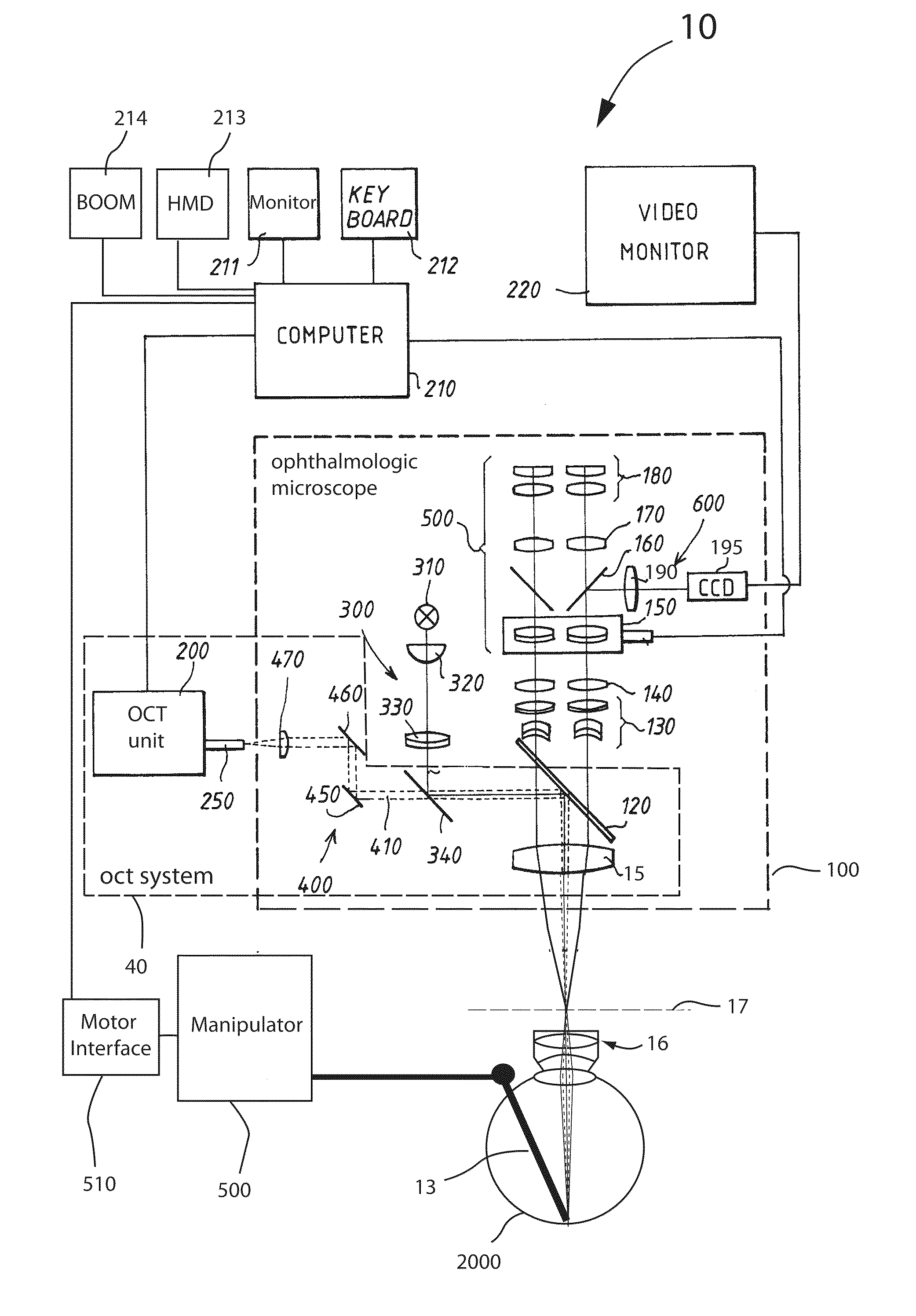
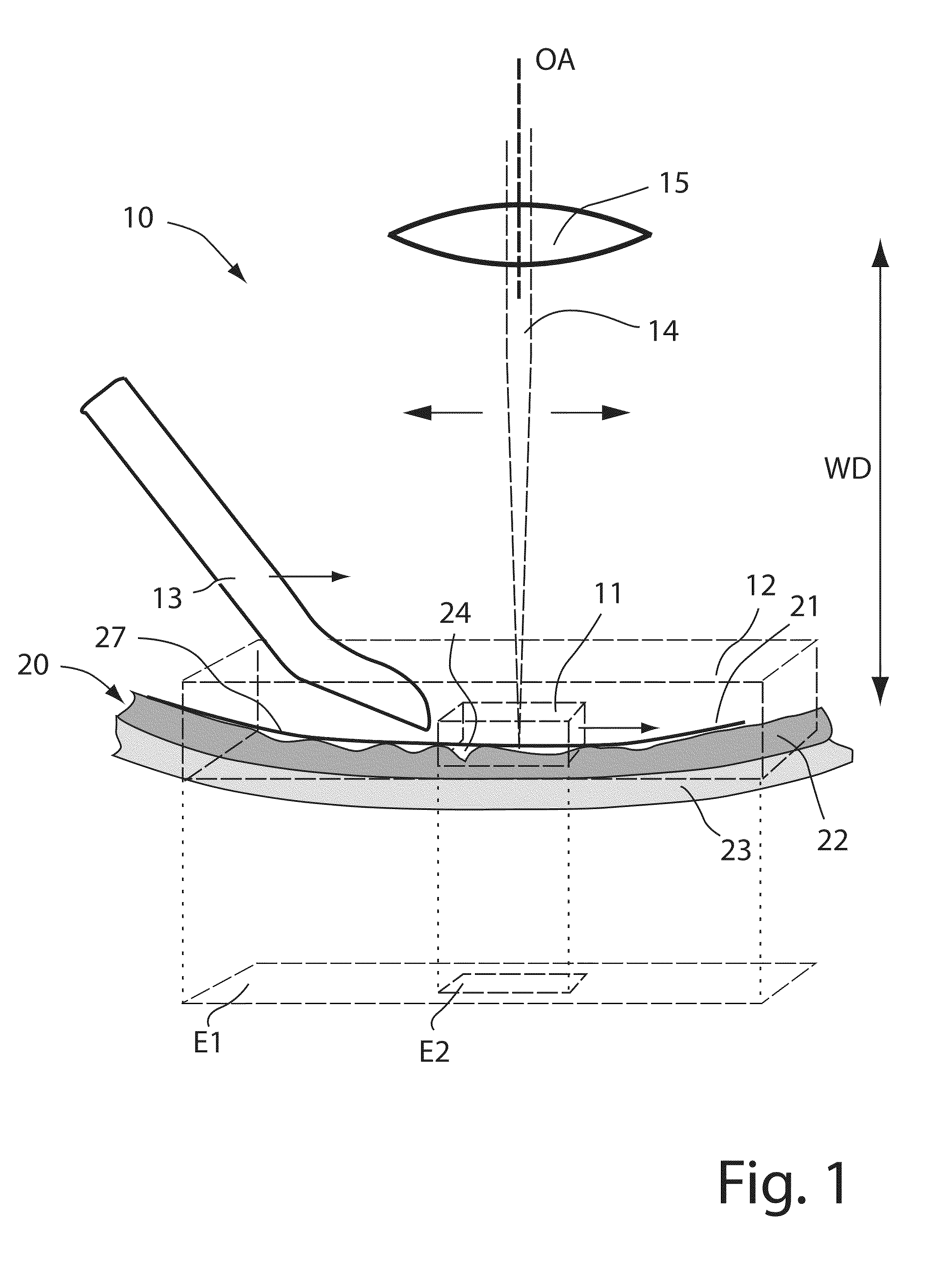
[0102]FIG. 1 schematically illustrates the method according to an embodiment. The optical system 10 comprises an objective lens 15 and a movable instrument 13. The movable instrument 13 may be for example forceps, scissors, a scalpel and / or a needle. The objective lens 15 focuses an OCT measuring beam 14 on the objects. Between the objective lens 15 and the objects, the OCT measuring beam 14 may further pass a contact ophthalmoscopy lens system 16 and the lens of the eye 2000 (not shown in FIG. 1). The optical system, which directs the OCT measuring beam has an optical axis OA, which is defined by the objective lens 15. The objects in this case are portions of the posterior portion of the eye 20, which comprises the epiretinal membrane 21, the retina 22 and the choroid 23. The movable surgical instrument 13 in this case is designed such as to allow the surgeon to peel off the epiretinal membrane 21 from the retina 22. The objective lens 15 is located at a working distance WD of appr...


PUM


Abstract

A method of visualizing objects using an optical system including an OCT system configured to obtain OCT data from voxels within a first volume having a first lateral extent includes obtaining position data indicative of a position of a predetermined portion of a movable instrument relative to the optical system and determining a first set of voxels from the voxels of the first volume based on the determined position such that at least 80% of the first set of voxels is located within a second volume having a second lateral extent with a size at least half the size of the first lateral extent. The method also includes obtaining OCT data of the first set of voxels, visualizing a representation of the OCT data of the first set of voxels, and repeating the steps of the method at a first repetition rate higher than 5 times per second.

Description

CROSS-REFERENCES TO RELATED APPLICATIONS[0001]The present application claims benefit under 35 U.S.C. §119(e) of U.S. Provisional Patent Application No. 61 / 295,376, filed on Jan. 15, 2010, entitled “System and Method for Visualizing Objects,” the disclosure of which is hereby incorporated by reference in its entirety for all purposes.BACKGROUND OF THE INVENTION[0002]The invention relates to a method of performing eye surgery using an optical coherence tomography (OCT) system and a movable surgical instrument.[0003]The invention also relates to a system for performing optical coherence tomography (OCT) assisted eye surgery with a movable surgical instrument.SUMMARY OF THE INVENTION[0004]Epiretinal membrane, also known as macular pucker is a disease of the eye, which is caused in particular by changes in the vitreous humor. Shrinkage and forward movement of the vitreous may cause traction or pulling on the retina, which can result in microscopic damages to its inner surface. The retina...

Claims


Application Information

Patent Timeline
IPC IPC(8): A61B3/14
CPCA61B3/113A61B3/102
Inventor HAUGER, CHRISTOPHMATZ, HOLGERWILZBACH, MARCO
Owner CARL ZEISS MEDITEC AG
Learn More