Optical wiring arrangement and optical transmission module

a technology of optical wiring and optical transmission module, which is applied in the field of optical wiring, can solve the problems of difficult to meet the bendability of conventional inter-substrat wiring, the difficulty of forming the layer of electric wiring and the layer of optical wiring on the same plane, and the mobility required in the application of electrical wiring in the electronic device, so as to reduce scraping, reduce breakage, and improve the effect of mobility

Inactive Publication Date: 2012-01-26
ORMON CORP
View PDF1 Cites 5 Cited by
  • Summary
  • Abstract
  • Description
  • Claims
  • Application Information

AI Technical Summary

Benefits of technology

[0020]One or more embodiments of the present invention provides an optical wiring and a light transmission module that satisfies the mobility required in

Problems solved by technology

In the electric/light co-mounted substrate, it is difficult that the layer of the electric wiring is used as the substrate and a layer of the optical wiring is stacked thereon.
Furthermore, forming the layer of the electric wiring and the layer of the optical wiring on the same plane is difficult due to the formation of the light guide.
The mobility required in the application to the wiring in the electronic device is difficult to be satisfied with the bendability of the conventional inter-substrate wiring.
With such contact, the degradation of the optical characteristics is more susceptible than the conventional inter-substrate wiring.
The film light guide may be also broken, scraped, or abraded in contact with the external structura

Method used


Image

  • Optical wiring arrangement and optical transmission module
  • Optical wiring arrangement and optical transmission module
  • Optical wiring arrangement and optical transmission module

Examples


application example

[0206](Application Example)

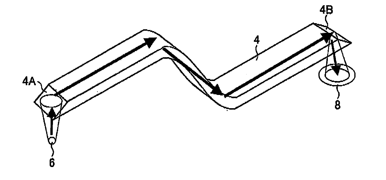
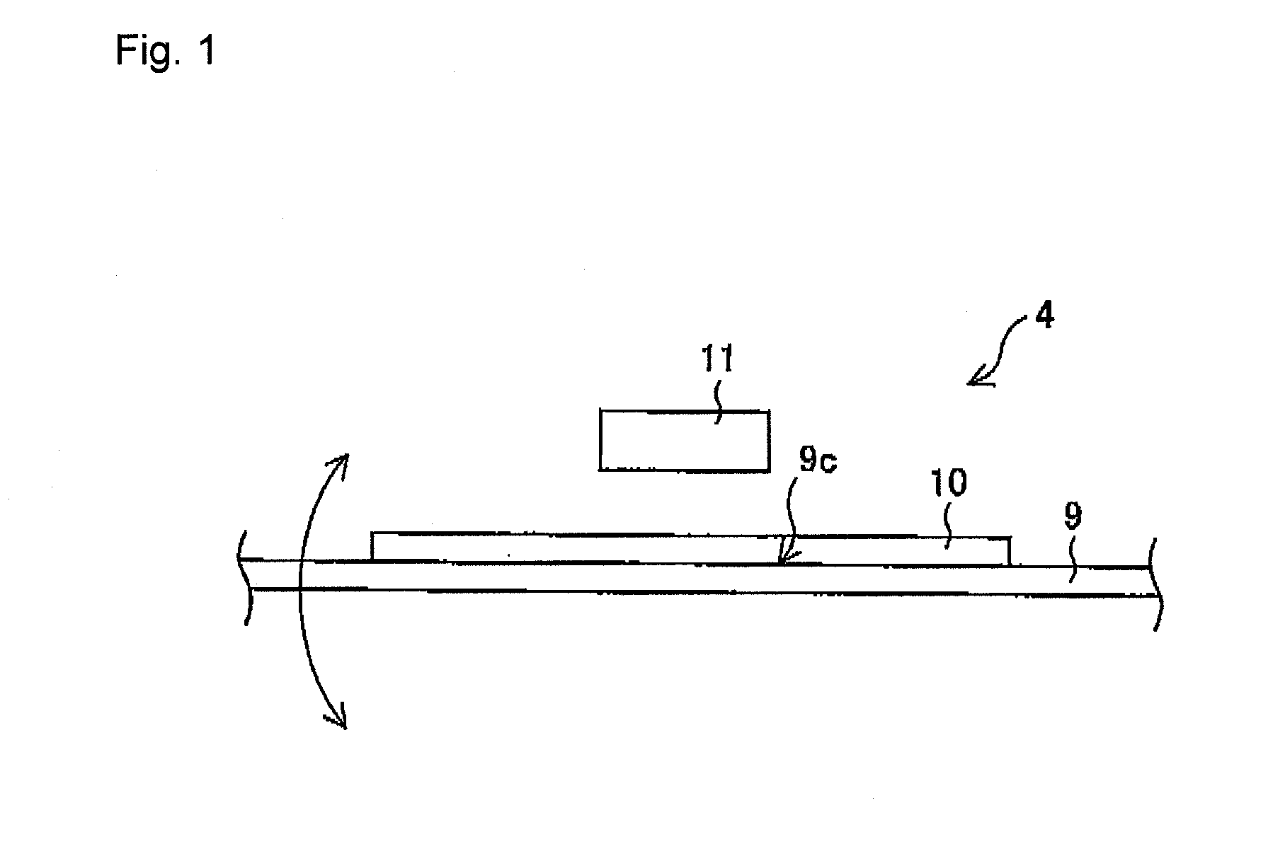
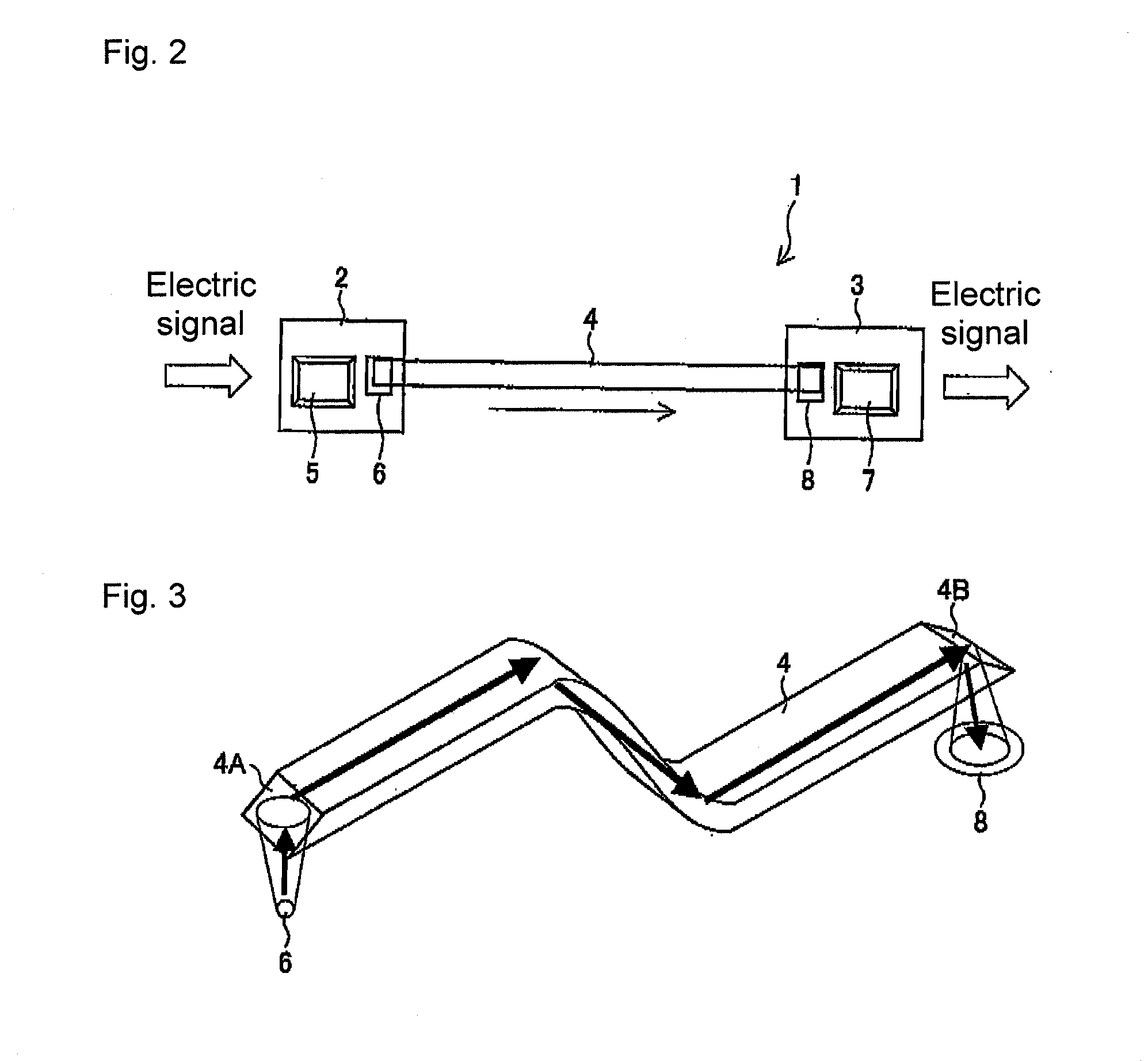
[0207]The optical wiring 4 of the present embodiment can be applied to the following application examples.

[0208]First, as a first application example, the optical wiring can be used for the hinge portion of a foldable electronic device such as a foldable portable telephone, a foldable PHS (Personal Handy-phone System), a foldable PDA (Personal Digital Assistant), and a foldable notebook computer.

[0209]FIGS. 20(a) to 20(c) show an example in which the optical wiring 4 is applied to a foldable portable telephone 40. In other words, FIG. 20(a) is a perspective view showing an outer appearance of the foldable portable telephone 40 incorporating the optical wiring 4.

[0210]FIG. 20(b) is a block diagram of a portion where the optical wiring 4 is applied in the foldable portable telephone 40 shown in FIG. 20(a). As shown in the figure, a control unit 41 arranged on a body 40a side in the foldable portable telephone 40, an external memory 42, a camera (digital came...


PUM


Abstract

An optical wiring mounted on an electronic device has a light transmission path for transmitting an optical signal. A function layer that reduces friction generated when coming in contact with a structural body in the electronic device to lower than when the light transmission path comes in contact with the structural body, and that bends according to deformation of the light transmission path, is arranged.

Description

TECHNICAL FIELD[0001]The present invention relates to an optical wiring for transmitting optical signals, and a light transmission module.BACKGROUND ART[0002]In recent years, an optical communication network enabling large capacity data communication at high speed is expanding. The optical communication network is expected to be mounted to commercial-off-the-shelf devices. The optical wiring is demanded to be used no different from the current electric cable as an inter-substrate wiring for higher speed and larger capacity of data transfer, noise countermeasures, and data transmission between substrates in a device. Such optical wiring includes an optical fiber, and a plastic optical fiber (POF).[0003]Conventionally, an optical cable that can be fabricated through a processing method suited for the application of long distance data transmission such as the optical fiber or the plastic optical fiber is mainly adopted for the inter-substrate wiring. The conventional inter-substrate wi...

Claims


Application Information

Patent Timeline
IPC IPC(8): G02B6/122
CPCB41J19/20G02B6/1221G02B6/43H01R35/02H05K1/148H04M1/0214H04M1/0274H05K1/0274H05K1/0393H04B10/225H01R2201/16H04B10/25G02B6/12G02B6/42
Inventor KASAI, MASAAKIHOSOKAWA, HAYAMIYASUDA, NARUSAMESHIMA, HIROSHITATARA, YOSHITAKAYOSHITAKE, NAOKI
Owner ORMON CORP
Why Eureka
Try Eureka