Surgical Procedures Using Instrument to Boundary Spacing Information Extracted from Real-Time Diagnostic Scan Data

a technology of real-time diagnostic scan data and surgical procedures, applied in the field of surgical procedures, can solve the problems of failure to meet the surgical goal, inadequate removal of healthy tissue, and excess removal of healthy tissue, and achieve the effect of less risk for patients

Inactive Publication Date: 2012-01-26
VANTAGE SURGICAL SYST
View PDF10 Cites 34 Cited by
  • Summary
  • Abstract
  • Description
  • Claims
  • Application Information

AI Technical Summary

Benefits of technology

[0006]is an object of some embodiments of the invention to provide an improved surgical procedure wherein the provision of more information to the surgeon, the more

Problems solved by technology

Surgical procedures: (1) involve certain risks to the patient, (2) take a certain time to perform, (3) take a certain experience or skill level by a surgeon, (4) result in the collateral damage of healthy tissue, (5) result in the excess removal of healthy tissue, (6) result in the inadequate removal of unhealthy tissue, (7) resu

Method used


Image

  • Surgical Procedures Using Instrument to Boundary Spacing Information Extracted from Real-Time Diagnostic Scan Data
  • Surgical Procedures Using Instrument to Boundary Spacing Information Extracted from Real-Time Diagnostic Scan Data
  • Surgical Procedures Using Instrument to Boundary Spacing Information Extracted from Real-Time Diagnostic Scan Data

Examples


first embodiment

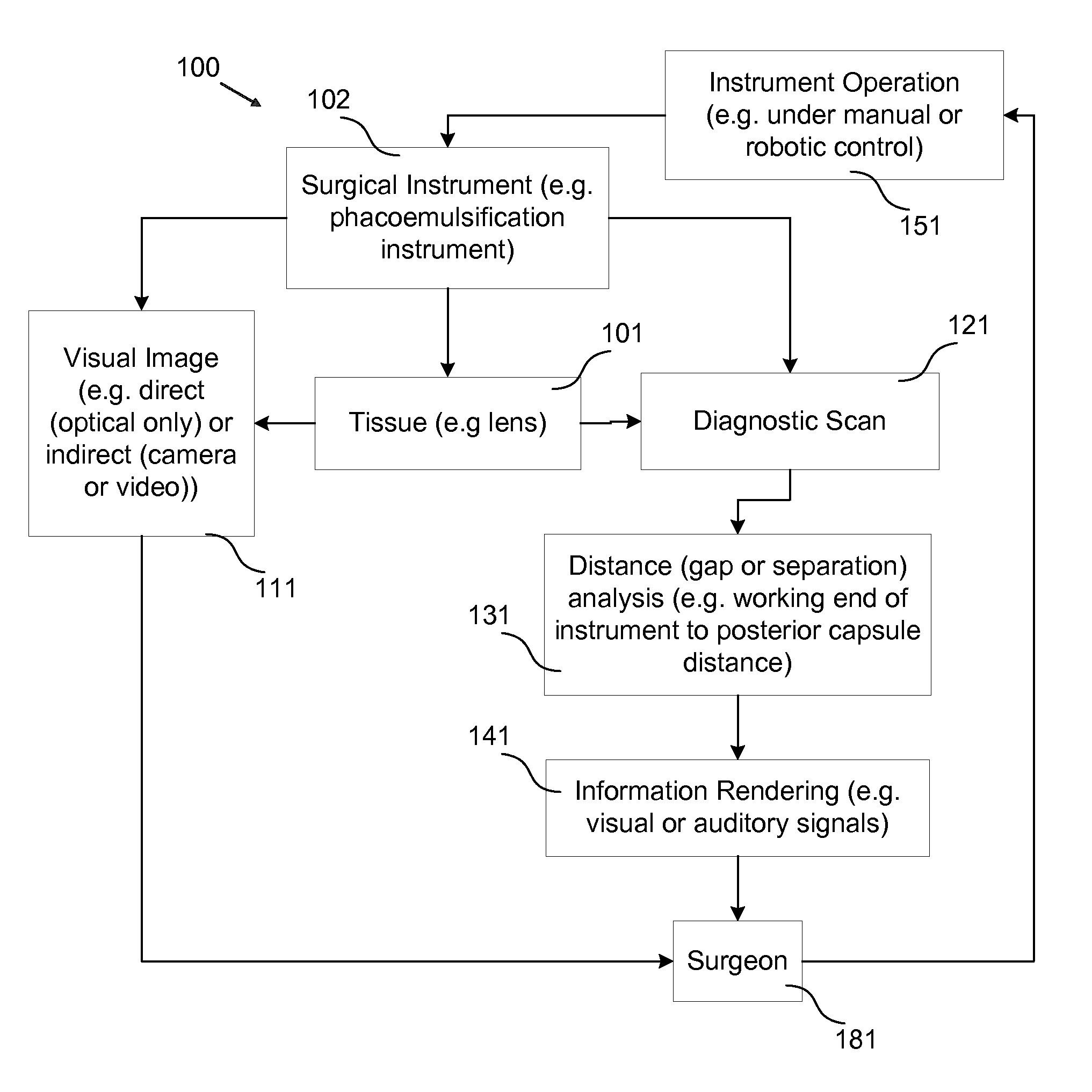
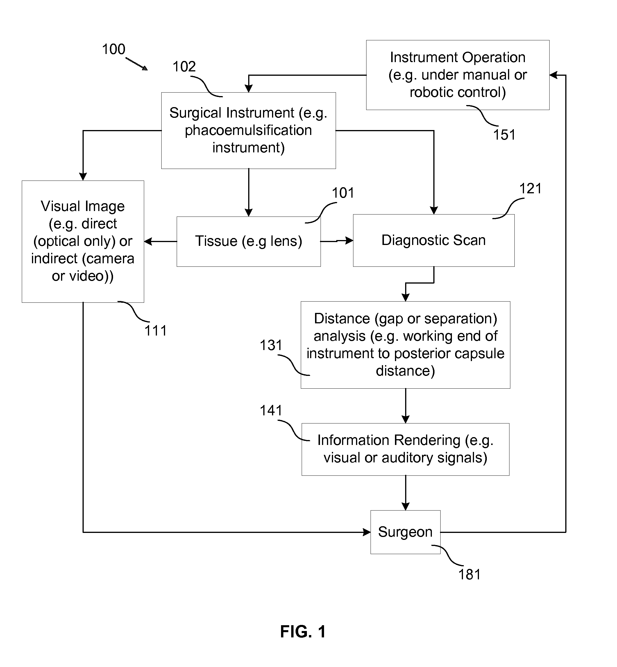
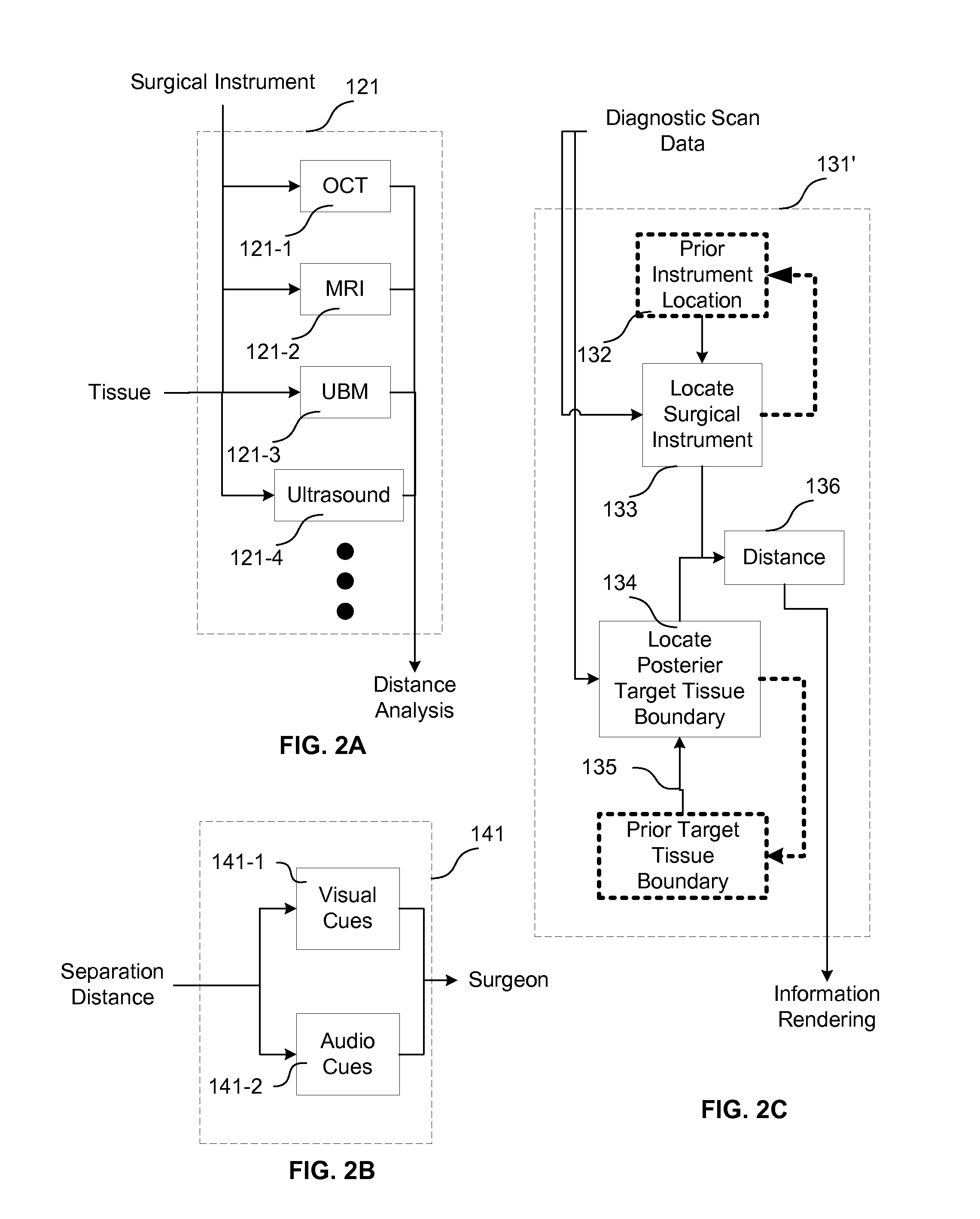
[0047]Variations of the first embodiment may obtain scan data form a variety sources and may obtain that data in a variety of forms. For example FIG. 2A provides several alternative types of diagnostic scans 121 that may be performed during a given surgery. In different types of surgeries different types of scans may be preferred due to different abilities to distinguish different tissue types, different resolutions available, different scanning speeds, different scanning logistics that are applicability to different surgical circumstances, and the like. In particular, FIG. 2A indicates for example scan types that the used: an OCT scan 121-1, an MRI scan 121-2, a UBM scan 121-3, and / or an ultrasonic scan 121-4. It is understood by those of skill in the art that other scan types may also be used in some alternative embodiments.

[0048]Variations of the first embodiment may provide and / or render distance, information into a variety of forms. FIG. 2B provides two examples of alternative ...

second embodiment

[0055]FIG. 3 provides a block diagram representing selected steps of the invention that is similar to the first embodiment of the invention with the exception that rendered information takes the form of a visual representation that is overlaid with real visual images that are presented to the surgeon.

[0056]Like elements between FIGS. 1 and 3 are labeled with like reference numerals with the exception that the elements of FIG. 3 use the 200 series while elements in FIG. 1 used the 100 series. Element 241 calls for the rendering to be in visual form which is combined with the visual image 211 of the surgical instrument 202 and tissue 201 before presentation to the surgeon. The combining or overlaying of these visual images may occur optically as described in incorporated U.S. patent application Ser. No. 13 / 164,671 or electronically while the images remain in a data form. The overlaying may occur using markerless tracking algorithms with or without electronic or optical feedback allowi...

third embodiment

[0057]FIG. 4 provides a block diagram representing selected steps of the invention that is similar to the second embodiment of the invention with the exception that in addition to the diagnostic scan data being used to provide distance information concerning the separation of a working end of the instrument and the posterior surface, the diagnostic scan data is also used to provide information concerning remaining thickness of material that is located between the working end of the instrument and the posterior surface, which thickness may be less than the distance when some of the intervening material has already been removed, visual information associated with the distance and thickness is then combined with the visual image of the instrument and tissue for presentation to the surgeon.

[0058]As with FIG. 3 like elements between FIGS. 4 and 3 are identified with like reference numerals with the exception that the reference numerals of FIG. 4 are presented in the 300 series as opposed...


PUM


Abstract

Specific embodiments of the invention are directed to improved phacoemulsification procedures involving the use of processed non-visual three-dimensional data (i.e. diagnostic scan data) to provide a surgeon with additional guidance (i.e. more than that generally obtained from visual observation of the working area) concerning the distance separating a working end of a phacoemulsification instrument and the posterior portion of the capsule of the eye during surgical procedures involving the removal of the crystalline lens of an eye (e.g. a cataract removal procedure). Such separation (i.e. distance or gap) information may be used to aid the surgeon in cutting or scoring the lens to a desired depth while minimizing the risk of penetrating the posterior portion of the capsule with the working end of the instrument. Some embodiments provide for the visual and/or auditory conveyance of distance information to the surgeon wherein visual information may be conveyed by overlaying it with real visual images of actual surface features viewed by the surgeon. Additional embodiments provide for overlaying visual representations of selected three-dimensional structure information (e.g. depths of troughs cut into the lens) with the real surface feature images viewed by the surgeon.

Description

RELATED APPLICATIONS[0001]This application claims the benefit of U.S. Provisional Patent Application No. 61 / 358,793, filed Jun. 25, 2010 and is a continuation in part of U.S. patent application Ser. No. 13 / 164,671 filed Jun. 20, 2011 which in turn claims benefit of U.S. Provisional Patent Application No. 61 / 356,150 filed Jun. 18, 2010. These applications are incorporated herein by reference as if set forth in full herein.FIELD OF THE INVENTION[0002]The present invention relates generally to the field of surgical procedures and more particularly to surgical procedures involving nearby boundary regions where surgical instrument penetration is to be minimized or eliminated (i.e. non-fly zones) and wherein computer generated feedback concerning separation distance between a surgical instrument and such boundaries is automatically calculated and optical or auditory feedback is provided to the surgeon to aid in the performance of the surgery. Specific embodiments of the invention relate t...

Claims


Application Information

Patent Timeline
IPC IPC(8): A61F9/007A61B17/3209A61B17/3205
CPCA61B19/2203A61B19/5244A61B2019/5214A61F9/00736A61B2019/5236A61B2019/5276A61B2019/5291A61B2019/5234A61B2090/3612A61B2090/3735A61B34/20A61B34/30A61B2090/374A61B2090/378A61B2090/365A61B5/0036A61B5/0066A61B5/055A61B5/7415A61B8/10A61B8/5223A61F9/00745A61F9/00754
Inventor HUBSCHMAN, JEAN-PIERRESCHWARTZ, STEVENWILSON, JASON T.TSAO, TSU-CHINGIBSON, JAMES S.
Owner VANTAGE SURGICAL SYST
Why Eureka
Try Eureka