Message transmission

a message and transmission technology, applied in the field of message transmission, can solve the problems of difficult to achieve such a short time period in an environment where control is highly centralised, take a long time, etc., and achieve the effect of speeding up the time taken for identified base stations, reducing the amount of traffic required, and reducing the amount of messages

Inactive Publication Date: 2012-01-26
ALCATEL LUCENT SAS
View PDF10 Cites 34 Cited by
  • Summary
  • Abstract
  • Description
  • Claims
  • Application Information

AI Technical Summary

Benefits of technology

[0007]Accordingly, when a message is received to be transmitted to user equipment within a particular geographical area of the telecommunications network, one or more multicast internet protocol (IP) addresses are identified. These multicast IP addresses are identified as being associated with base stations which provide coverage within the particular geographical area. The message is then transmitted with the multicast IP address over the IP network to be received by base stations. In this way, each base station identified by the multicast IP address will simultaneously receive the message, rather than each individual base station needing to have its own dedicated message sent to each base station sequentially. It will be appreciated that this not only significantly speeds the time taken for identified base stations to receive the message, it also reduces the amount of traffic required since the message is transmitted in a multicast manner. Furthermore, only those base stations which are associated with the multicast IP address will act on the message, all other base stations may ignore it. Accordingly, this helps to ensure that the message is only relayed to user equipment in a particular geographical region, rather than being delivered to all user equipment supported by all base stations associated with a particular controller.
[0008]In other words, when an message is received which is to be delivered to all the base stations within a specific area, the message is sent to all base stations that need to receive it by sending the message to all the multicast addresses that are intended to cover the entire geographical region to be alerted. This significantly reduces the number of message that need to be sent to the intended base stations in order for them to receive the message. For example, should a region including 3,000 base stations be affected, a unicast solution would be to send 3,000 messages (excluding retransmissions due to errors), one to each base station. In a multicast arrangement, it may sufficient to send a single, or typically no more than a few, messages to a single multicast address. It will appreciated that this reduces the amount of messages to be sent by orders of magnitude and enable tight time constraints on the delivery of messages to be achieved at an acceptable cost even in an architecture having highly centralised controllers.

Problems solved by technology

Achieving such a short time period in an environment where control is highly centralised is difficult to achieve.
This is because each message is transmitted to each base station sequentially and so if, for example, a controller (such as an mobility management entity) needs to communicate with a large number of base stations then this can take a long time.

Method used


Image

  • Message transmission
  • Message transmission
  • Message transmission

Examples


Embodiment Construction

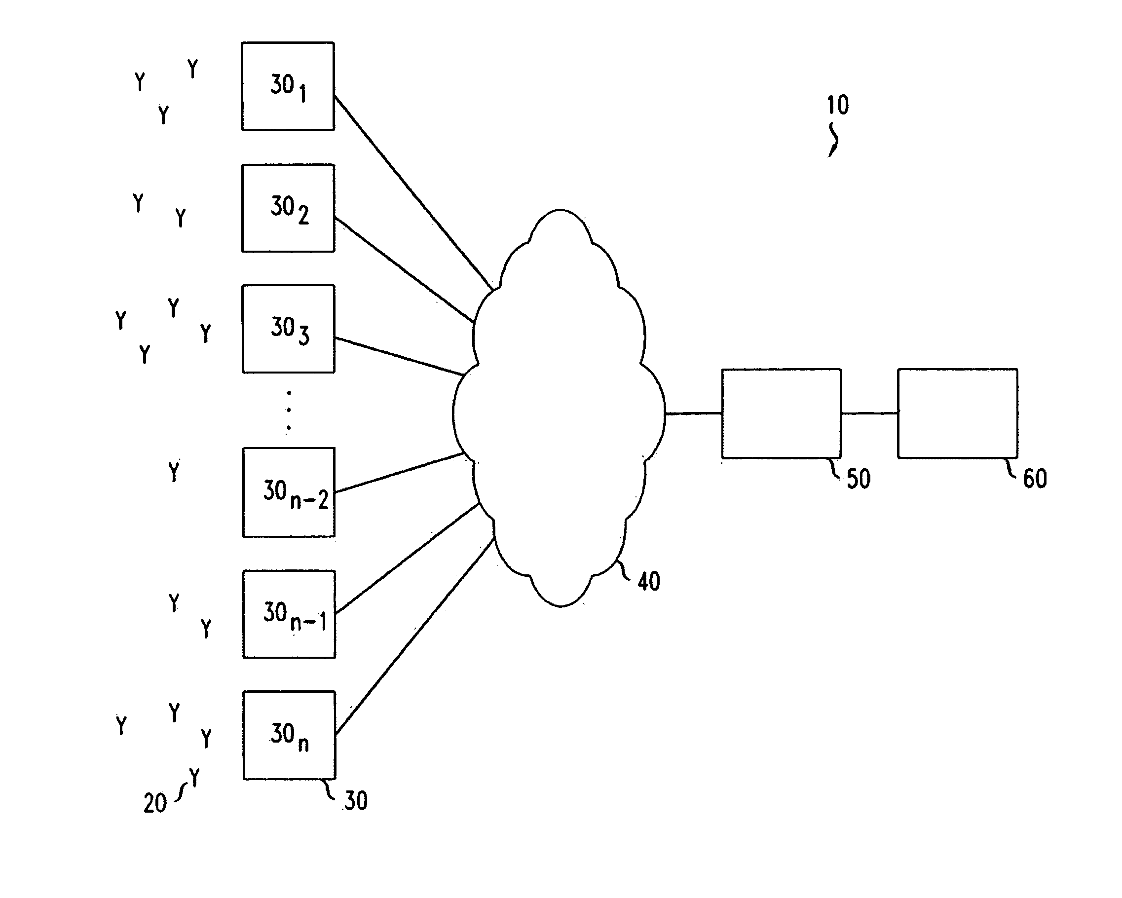
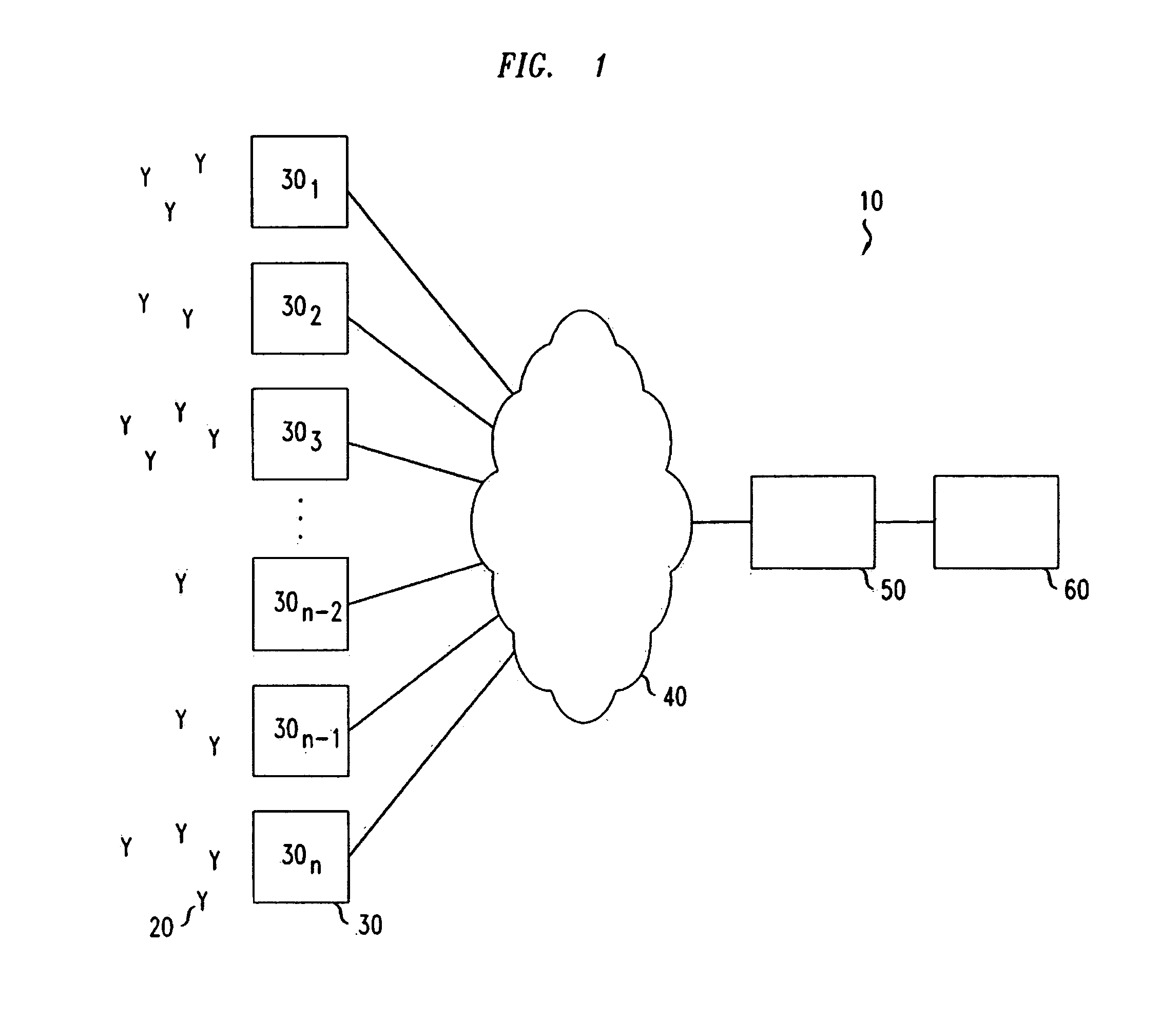
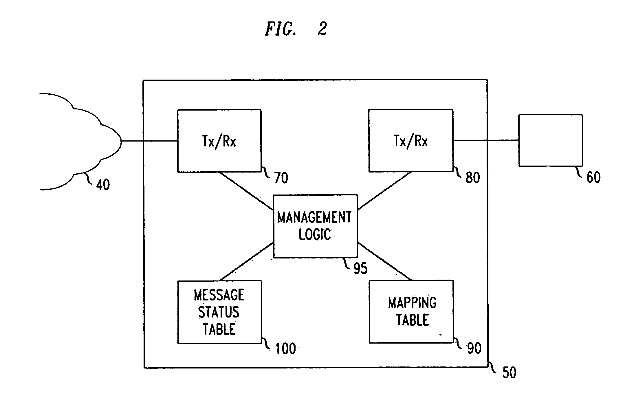
[0047]FIGS. 1 to 3 illustrates the main components of a telecommunications network, generally 10, accordingly to one embodiment. As shown in FIG. 1, user equipment 20 roam through the telecommunications network 10. Base stations 301 to 30N are provided which support respective cells. A number of such base stations 301 to 30N are provided, which are distributed geographically in order to provide a wide area of wireless communications coverage to the user equipment 20. When user equipment 20 is within a cell supported by a base station 301 to 30N then communications may be established between the user equipment 20 and that base station 301 to 30N over an associated radio link. Each base station 301 to 30N supports a number of sectors within each cell. Typically, a different antenna within a base station 301 to 30N supports an associated sector. Accordingly, each base station 301 to 30N has multiple antennas and signals sent through the different antennas are electronically weighted to...


PUM


Abstract

A method of transmitting a message to user equipment within a telecommunications network, a controller operable to transmit a message to user equipment within a telecommunications network, a base station and a computer program product are disclosed. The method comprises the steps of: receiving a message having message content to be transmitted to user equipment within a predefined geographical area of the telecommunications network; identifying at least one multicast IP address designated as being associated with base stations providing telecommunications coverage with user equipment within the predefined geographical area; and transmitting the message content within at least one multicast message, each multicast message using a corresponding one of the at least one multicast IP address, over an IP network to base stations providing telecommunications coverage within the predetermined geographical area for onward transmission to user equipment. In this way, each base station identified by the multicast IP address will simultaneously receive the message, rather than each individual base station needing to have its own dedicated message sent to each base station sequentially. This not only significantly speeds the time taken for identified base stations to receive the message, it also reduces the amount of traffic required since the message is transmitted in a multicast manner. Furthermore, only those base stations which are associated with the multicast IP address will act on the message, all other base stations may ignore it. This helps to ensure that the message is only relayed to user equipment in a particular geographical region, rather than being delivered to all user equipment supported by all base stations associated with a particular controller.

Description

FIELD OF THE INVENTION[0001]The present invention relates to a method of transmitting a message to user equipment within a telecommunications network, a controller operable to transmit a message to user equipment within a telecommunications network, a base station and a computer program product.BACKGROUND OF THE INVENTION[0002]It is often desired to transmit a message to many user equipment within a telecommunications network. For example, government agencies wish to communicate an alert warning of an impending emergency such as, for example, a tsunami, earthquake or other potential emergency, to user equipment within a telecommunications network in order to attempt to avert or mitigate the consequences of such a potentially catastrophic event.[0003]In a telecommunications network, such as that defined by the Third Generation Partnership Project (3GPP) in document S2-085143, it is envisaged that a cell broadcast entity (such as a government agency) sends an emergency broadcast reque...

Claims


Application Information

Patent Timeline
Patent Type & Authority Applications(United States)
IPC IPC(8): G06F15/16
CPCH04L12/1868H04L12/1895H04L12/189H04L12/1881
Inventor DREVON, NICOLASCASATI, ALESSIO
Owner ALCATEL LUCENT SAS
Why Eureka
Try Eureka