
Loop cutter knife fixture with replaceable blades

a technology of blade replacement and blade change, which is applied in the direction of shearing tools, metal-working equipment, shearing equipment, etc., can solve the problem of relatively expensive changeover process of knife fixtur

Inactive Publication Date: 2012-02-02
J R SIMPLOT
View PDF7 Cites 25 Cited by
  • Summary
  • Abstract
  • Description
  • Claims
  • Application Information

AI Technical Summary

Benefits of technology

[0008]The slab and strip knife blades are thus carried by the blade holder for rotation in the production flow path to cut respectively a generally helical slab from each vegetable product and then to split that slab into multiple helical loops of different diametric sizes which are discharged for further processing. When the slab and / or strip blades require re-sharpening, the cost-efficient slab and strip blades are disassembled quickly and easily from the blade holder, and replaced by similar new or re-sharpened slab and strip blades for resumed production.
[0009]In one preferred form of the invention when the knife fixture in used in an hydraulic cutting system, the blade holder additionally has at least one and preferably multiple open passages formed therein to accommodate relatively unrestricted flow of the hydraulic fluid, such as water, therethrough without requiring fluid bypass of the knife fixture. These open passages may take the form of axially open slots formed in the blade holder, with each slot preferably formed on a common radius.

Problems solved by technology

One common problem associated with rotary knife fixtures designed to cut potatoes and the like into spiral or helical pieces relates to the need for periodic re-sharpening of the slab and strip blades.
This knife fixture changeover process is relatively costly, since it is necessary to remove the entire knife fixture from the cutting apparatus, and to maintain multiple and relatively expensive spare knife fixtures with re-sharpened slab and strip knives in order to maintain several parallel cutting lines in production service.

Method used


Image

  • Loop cutter knife fixture with replaceable blades
  • Loop cutter knife fixture with replaceable blades
  • Loop cutter knife fixture with replaceable blades

Examples


Embodiment Construction

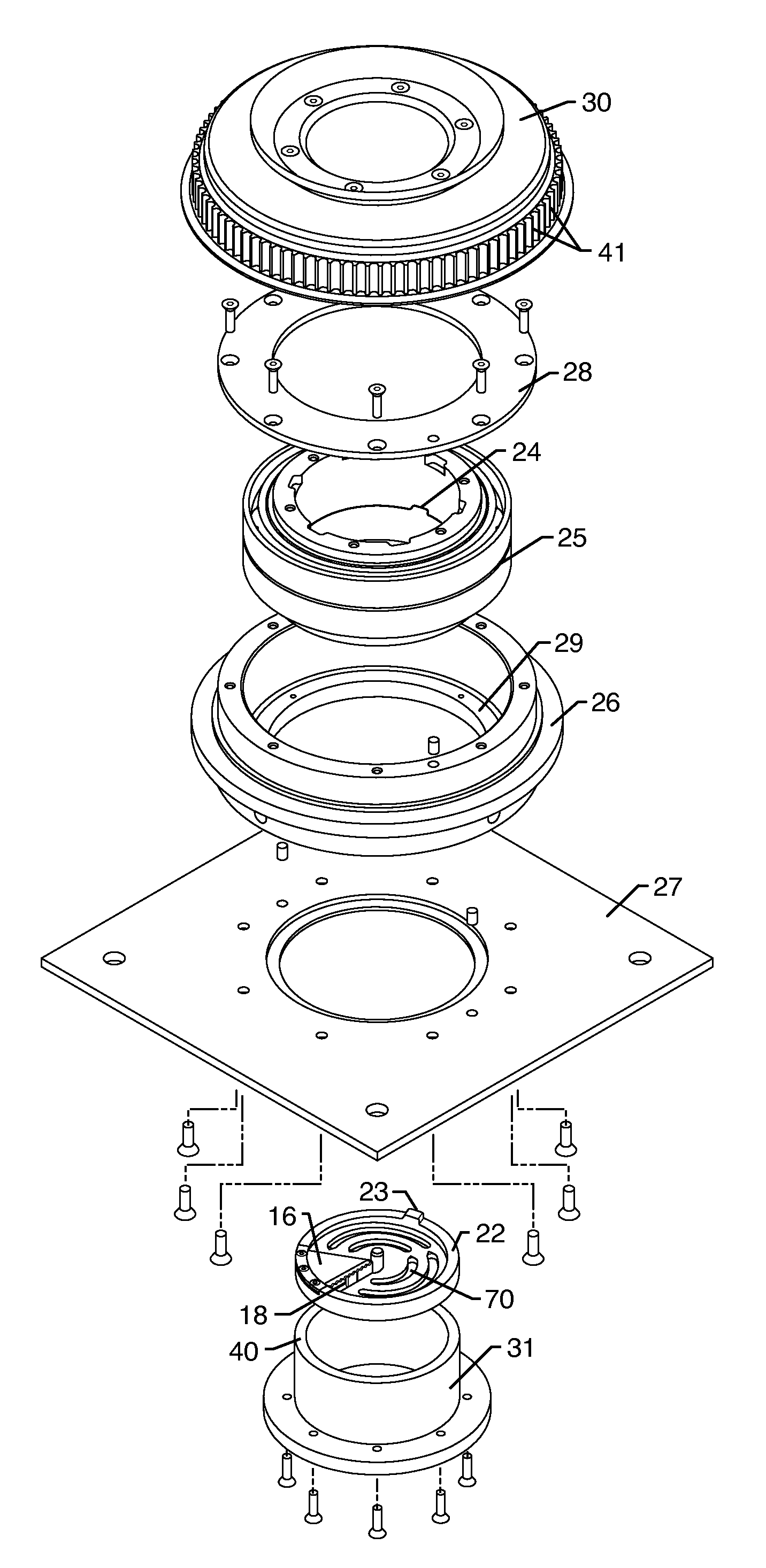
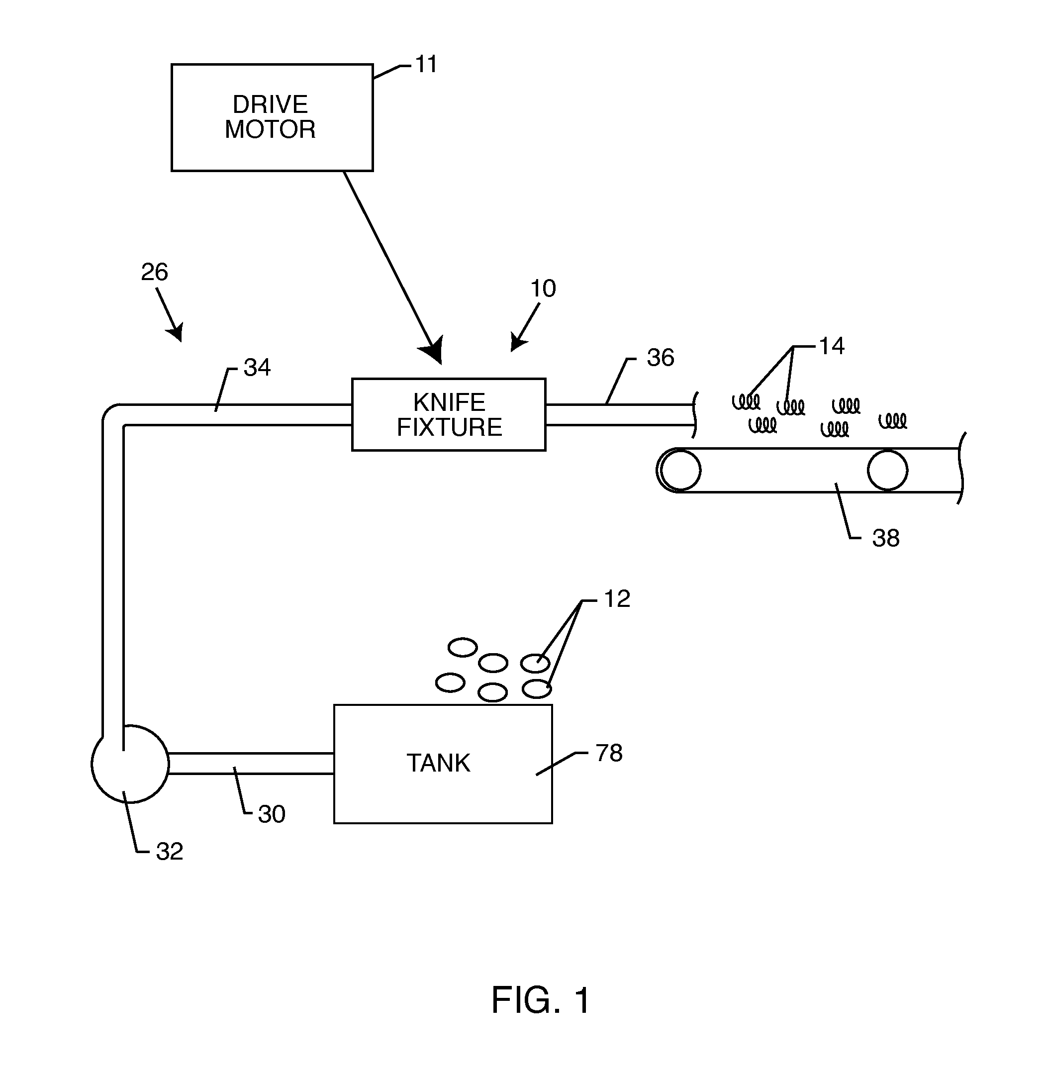
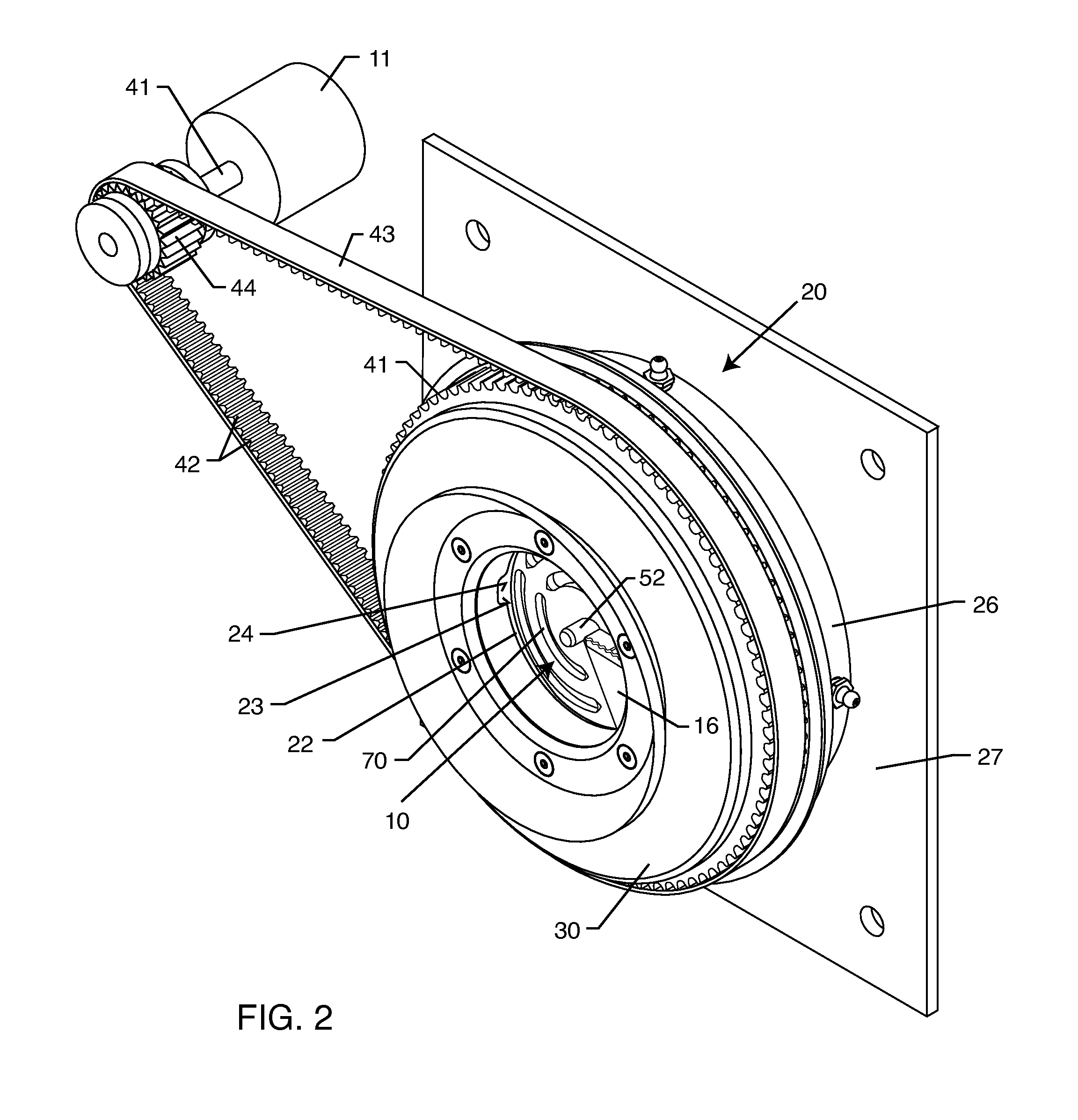
[0018]As shown in the exemplary drawings, an hydraulic cutting system comprises a conventional so-called water knife fixture referred to generally in FIG. 1 by the reference numeral 10 for cutting vegetable products such as whole potatoes 12 into spiral or helical shaped strips 14 for subsequent processing. The present invention comprises a rotary driven knife fixture 10 (FIGS. 2-6) for installation into the cutting system and for rotatable driving by means of a drive motor 11 or the like. The knife fixture 10 includes a relatively inexpensive or cost-efficient slab blade 16 in combination with at least one and preferably multiple strip blades 18 adapted for relatively quick and easy disassembly from the knife fixture 10 when blade re-sharpening is required, and for similarly quick and easy assembly of new or re-sharpened blades 16, 18 with the knife fixture 10 for resumed production.

[0019]FIG. 1 shows the cutting system in the form of an hydraulic cutting system comprising a tank 7...


PUM

PropertyMeasurementUnit
Flow rateaaaaaaaaaa
Sizeaaaaaaaaaa
Shapeaaaaaaaaaa

Abstract

A loop cutter knife fixture for cutting vegetable products such as raw potatoes into spiral or helical loops. The knife fixture includes a circular blade holder adapted to be rotatably driven within a vegetable product flow path. The blade holder includes a central core cutter in combination with a spiral base plate defining a radial slot between axially spaced upstream and downstream ends thereof. Small slits are formed in this base plate for seated reception of preferably multiple U-shaped strip blades, which are in turn overlaid and clamped in place beneath a generally pie-shaped slab blade having a sharpened knife edge exposed at the base plate radial slot and held in place by preferably multiple clamp screws. The strip blades and / or the slab blade are formed from an inexpensive material, such as sheet metal or the like, whereby blade changeover is quick and economical.

Description

BACKGROUND OF THE INVENTION[0001]This invention relates generally to improvements in devices and methods for cutting food products such as vegetable products, and particularly such as raw potatoes and the like, into spiral or helical shaped pieces. More particularly, this invention relates to a rotatably driven knife fixture having relatively inexpensive and easily changed cutting blades.[0002]Production cutting systems and related knife fixtures are generally well known in the art for cutting vegetable products such as raw potatoes into spiral or helical shaped pieces, preparatory to further production processing steps such as blanching and parfrying. In this regard, one typical production system comprises an hydraulic cutting system wherein a so-called water knife fixture is mounted along the length of an elongated tubular conduit. A pumping device is provided to entrain the vegetable product such as raw potatoes within a propelling water flume for cutting engagement with knife bl...

Claims


Application Information

Patent Timeline
IPC IPC(8): B26D1/29B26D7/06
CPCB26D7/2614B26D1/29Y10T83/6472Y10T83/9403
Inventor WALKER, DAVID B.NEEL, ALLEN J.
Owner J R SIMPLOT
Learn More