Ultrasonic diagnosis apparatus and method for constructing distribution image of blood flow dynamic state

a dynamic state and ultrasonic diagnosis technology, applied in ultrasonic/sonic/infrasonic diagnostics, instruments, tomography, etc., can solve the problems of difficult to distinguish the portal vein from the artery, the cta sometimes places a load on the patient, etc., to facilitate the comparison of variations in the blood flow dynamics

Active Publication Date: 2012-02-02
FUJIFILM HEALTHCARE CORP
View PDF11 Cites 22 Cited by
  • Summary
  • Abstract
  • Description
  • Claims
  • Application Information

AI Technical Summary

Benefits of technology

[0016]According to the present invention, it is possible to evaluate the blood flow dynamics starting from the heart by using the time-intensity curve (TIC), and display in color,

Problems solved by technology

On the other hand, the CTA sometimes places a load on a patient, due to exposure to X-rays and administration of the contrast agent.
However, since the artery runs in parallel

Method used


Image

  • Ultrasonic diagnosis apparatus and method for constructing distribution image of blood flow dynamic state
  • Ultrasonic diagnosis apparatus and method for constructing distribution image of blood flow dynamic state
  • Ultrasonic diagnosis apparatus and method for constructing distribution image of blood flow dynamic state

Examples


first embodiment

[0040]Hereinafter, preferred embodiments of the present invention will be explained with reference to the accompanying drawings.

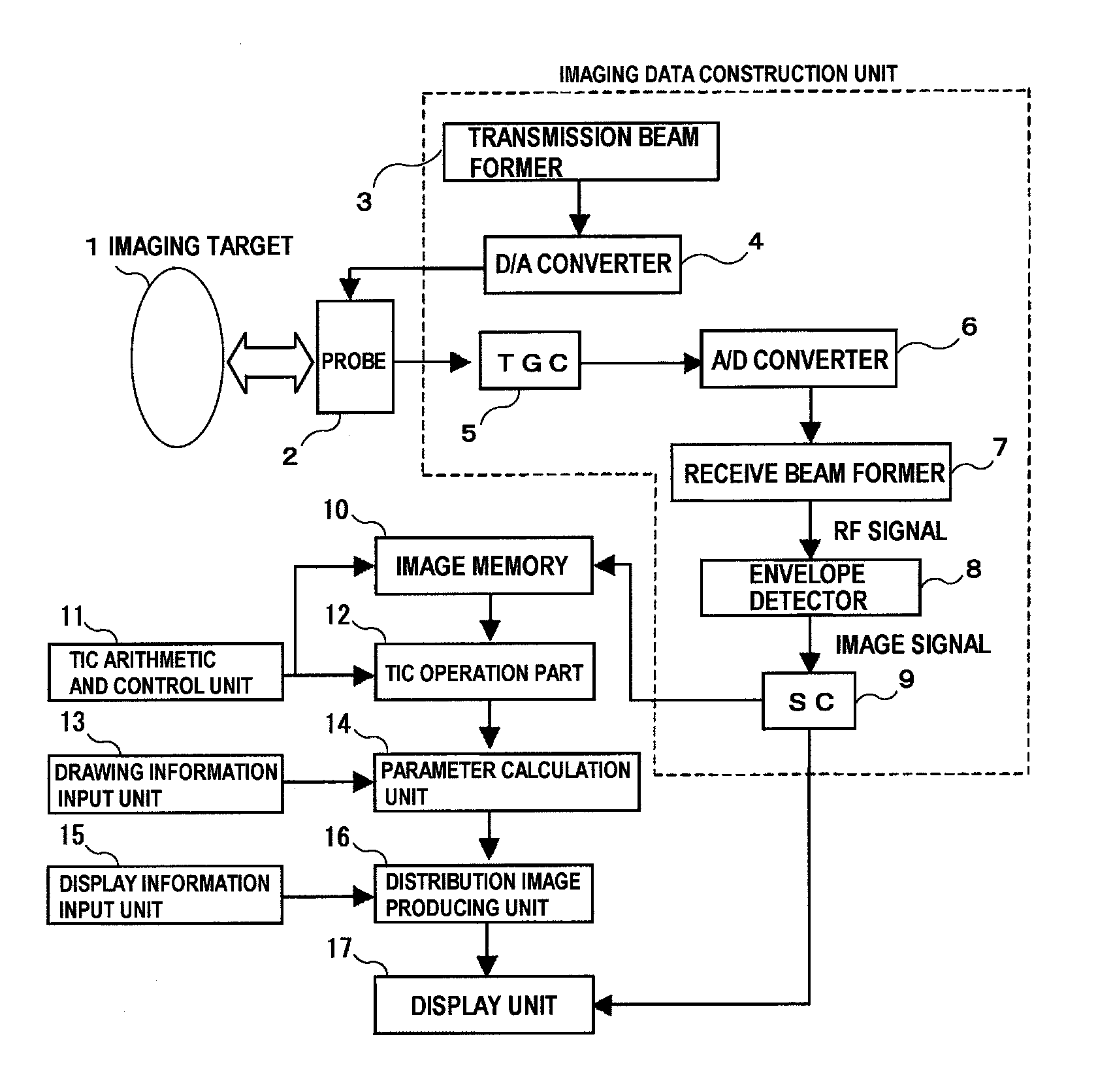
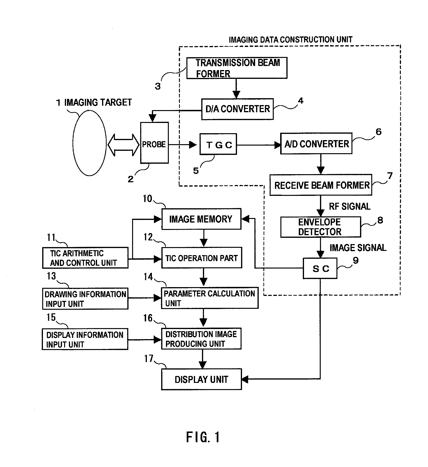
[0041]FIG. 1 is a block diagram showing the ultrasonic diagnostic apparatus (image display apparatus) according to the first embodiment.

[0042]This apparatus includes, a probe 2 for transmitting and sending ultrasonic signals to and from an imaging target 1, a transmission beam former 3 and a receive beam former 7 for providing a predetermined time delay to form desired transmission and receiving beams on piezoelectric elements constituting the probe 2, a D / A converter 4 for converting a transmitted signal from digital to analog, an A / D converter 6 for converting a received signal from analog to digital, a TGC (time gain controller) 5 for compensating for amplitude attenuation that occurs in the course of propagation of ultrasonic signals inside a living body, an envelope detector 8 for detecting a received RF (radio frequency) signal and converting the sign...

second embodiment

[0088]Hereinafter, with reference to the accompanying drawings, the second embodiment of the present invention will be explained.

[0089]The ultrasonic diagnostic apparatus (image display apparatus) according to the second embodiment relates to a technique which three-dimensionally expands the technique described as the first embodiment. FIG. 19 illustrates a configuration of the apparatus. A shape, an internal structure, and an operation mode of the probe 2 are not particularly limited, as far as it is capable of imaging three-dimensional information. It may be a probe having a one-dimensional array as described in the first embodiment, mechanically movable with a drive unit such as a motor, or a probe having a two-dimensional array.

[0090]The transmission beam former 3 is provided with a wave transmission controller 19, which controls a wave transmission sequence for acquiring image data of multiple different cross sections. The wave transmission sequence is determined according to a...


PUM


Abstract

An ultrasonic diagnostic apparatus is provided for displaying a color map on which a difference in blood flow dynamics is reflected. Setting a test subject who is administered a contrast agent is assumed as an imaging target, and a probe transmits and receives ultrasonic waves to and from the target for contrast imaging. Image data is constructed based on signals received by the probe and a time-intensity curve is generated from intensity values of the image data. According to the time-intensity curve, a value of a predetermined parameter is calculated for producing a distribution image of blood flow dynamics. The distribution image (color map) of the blood flow dynamics is produced from the parameter value. The color map is a two-dimensional or a three-dimensional image being color-coded according to the parameter value. At least one of the followings may be used as the parameter; a contrast agent inflow start time, a balanced intensity arrival time, a contrast agent disappearance start time, a contrast agent duration, a preset threshold arrival time, an intensity increase rate, an intensity decrease rate, intensity of balanced state, and a total flow amount.

Description

TECHNICAL FIELD [0001]The present invention relates to a technique which transmits an ultrasonic wave directed inside a living body and performs imaging of information inside the living body according to a signal being received, and more particularly, it relates to an ultrasonic diagnostic apparatus for calculating information as to a bloodstream based on an image taken by using a contrast agent, and creating a picture to be displayed.BACKGROUND ART [0002]An ultrasonic diagnostic apparatus is a type of imaging apparatus generally employed in a medical field, together with an MRI system and a CT scanner, and characterized by compact in size, a high spatial and time resolution, and the like. In recent years, along with the widespread use of ultrasonic contrast agent, a vessel imaging technique and a tumor imaging technique have been developed, and therefore, expectations are rising for improved diagnostic performance.[0003]The bloodstream around a tumor or inside the tumor indicates n...

Claims


Application Information

Patent Timeline
IPC IPC(8): G06K9/00
CPCA61B8/06A61B8/13A61B8/463A61B8/469G01S15/8993A61B8/483G01S7/52071G01S15/8979A61B8/481
Inventor YOSHIKAWA, HIDEKIAZUMA, TAKASHI
Owner FUJIFILM HEALTHCARE CORP
Why Eureka
Try Eureka