Method of installing a hydroelectric turbine generator

a hydroelectric turbine and generator technology, applied in sea energy generation, tidal stream/damless hydropower, pipe laying and repair, etc., can solve the problems of inability to release the brake, the turbine cannot start spinning during installation,

Inactive Publication Date: 2012-02-02
OPENHYDRO IP
View PDF18 Cites 19 Cited by
  • Summary
  • Abstract
  • Description
  • Claims
  • Application Information

AI Technical Summary

Benefits of technology

[0039]The submarine power cable and the generator cable of the installed generator provide a mooring ...

Problems solved by technology

As the turbine generator is being lowered into position on site, it is impossible for the turbine to start spinning during installation.
As the control signal is transmitted via the submarine power cable, it is impossible for the brake to be released with...

Method used


Image

  • Method of installing a hydroelectric turbine generator
  • Method of installing a hydroelectric turbine generator
  • Method of installing a hydroelectric turbine generator

Examples


Embodiment Construction

[0045]An embodiment of the invention will now be described, by way of example only, with reference to the accompanying drawings, in which:

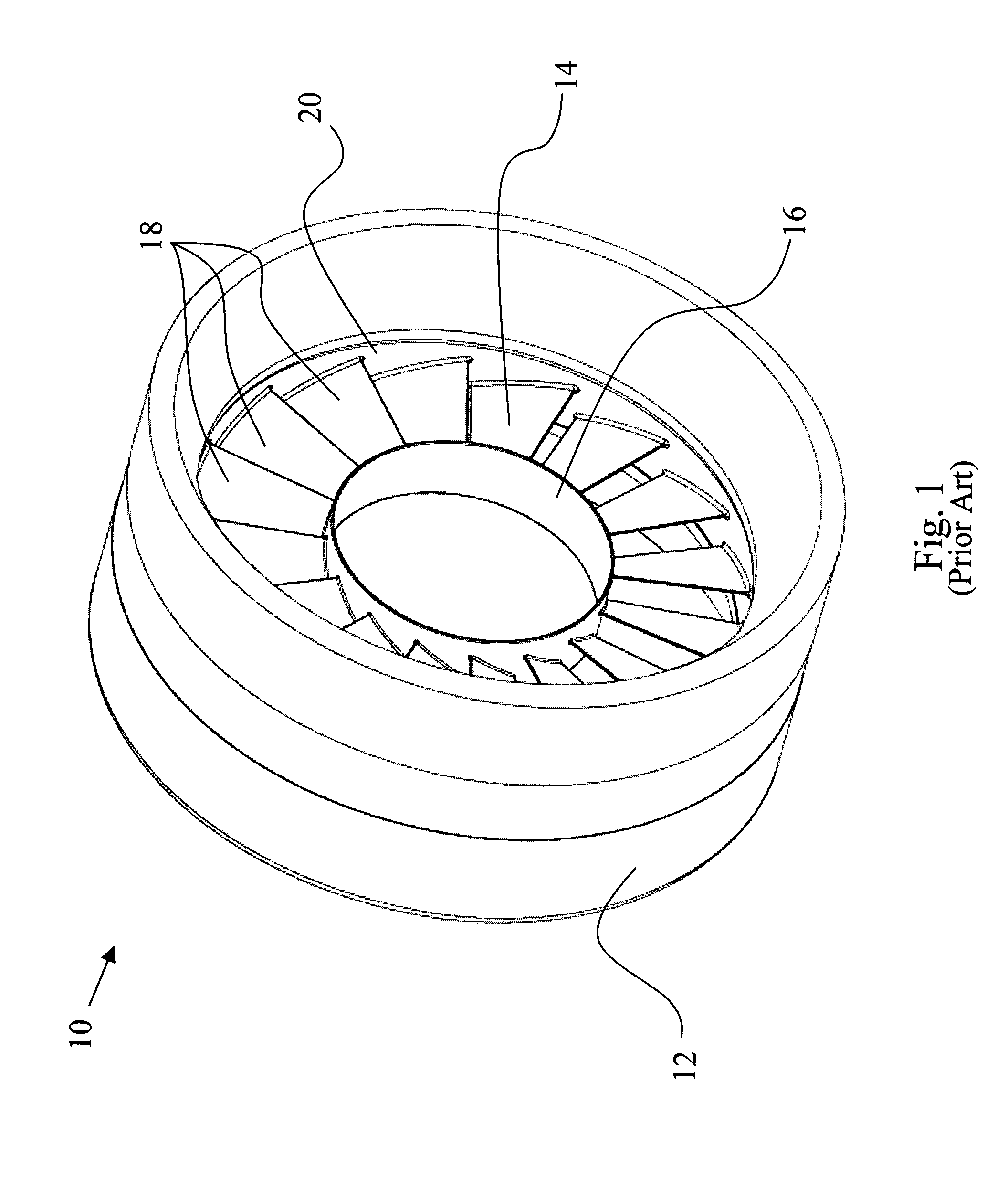
[0046]FIG. 1 is an isometric view of a prior art hydroelectric turbine generator;

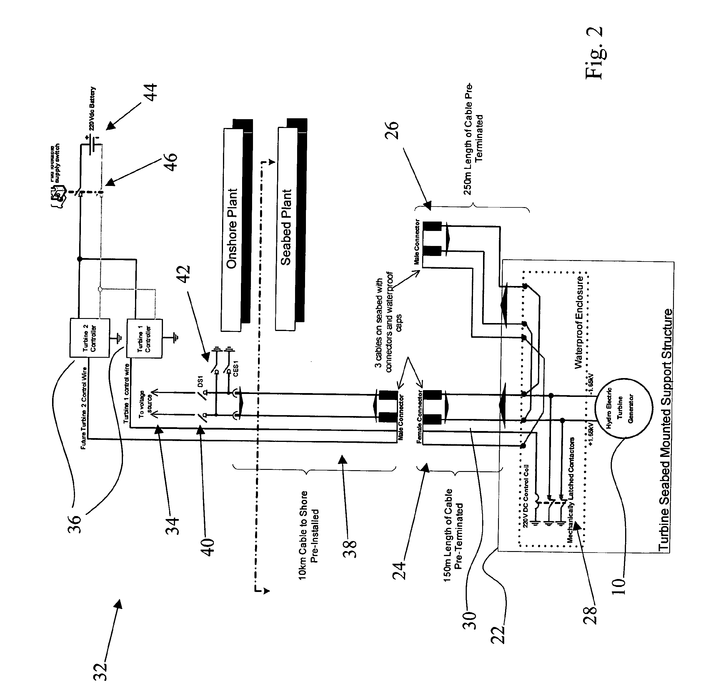
[0047]FIG. 2 is an outline of a sample configuration used for the installation and connection of a hydroelectric turbine generator to a supply grid;

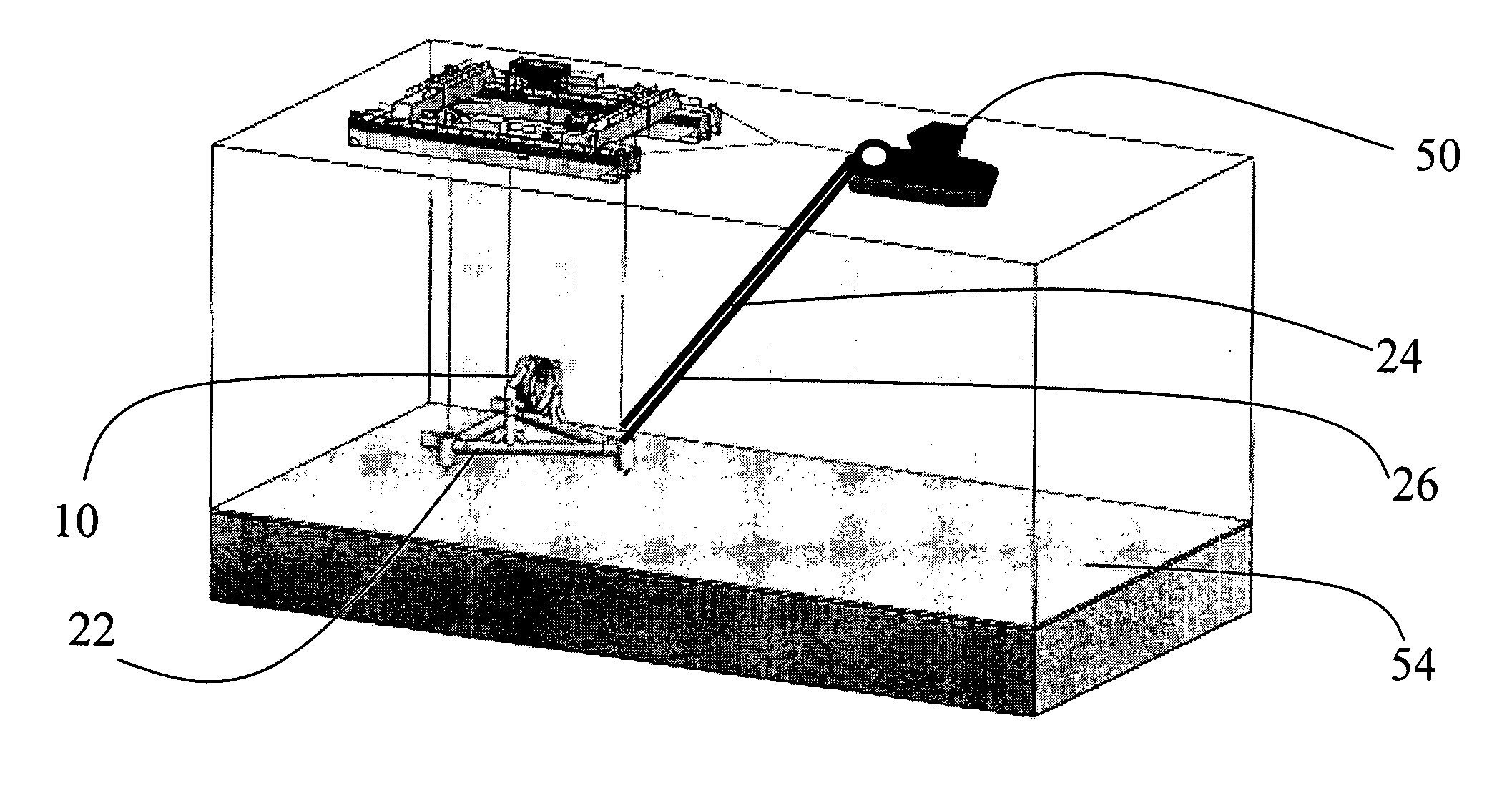
[0048]FIG. 3 is a view of an installation vessel and a hydroelectric turbine generator prior to deployment at an installation site; and

[0049]FIG. 4 is a view of an installation vessel and a hydroelectric turbine generator after deployment at an installation site.

[0050]With reference to FIG. 2, an overall view is presented of a sample circuit scheme for the installation of a hydroelectric turbine generator 10. The generator 10 is installed at an installation site in an area of tidal flow, the generator 10 being provided on a seabed mounted support structure 22. The generator 10 further comprises a generator cable 24, operab...


PUM


Abstract

A method of installing an off-shore tidal hydroelectric turbine generator is described. The method provides for a number of safety features, ensuring that all components are safe to handle during the installation operation, and also ensuring that the turbine will not start spinning during the installation operation.

Description

FIELD OF THE INVENTION[0001]This invention relates to a method of safely installing a sub sea tidal hydroelectric turbine generator.BACKGROUND OF THE INVENTION[0002]The increased interest in environmental awareness, and a reluctance to rely on non-renewable sources of energy, has led to greater usage of renewable energy systems, e.g. solar power, wind power, thermal power, and tidal power. The latter involves the installation of turbine generators in an area of tidal flow, and converts the energy of the tides into electrical power.[0003]With reference to FIG. 1, a direct-drive shaftless permanent magnet hydroelectric turbine generator is described in PCT Application No. PCT / EP2007 / 006258. The generator 10 comprises a ring-shaped stator 12 and a rotor 14, the stator 12 having a plurality of coils (not shown) located about the circumference of the stator 12. The rotor 14 comprises an inner rim 16, which defines an open centre. The rotor 14 further comprises an array of generally radia...

Claims


Application Information

Patent Timeline
IPC IPC(8): H02G1/10H02G9/02
CPCH02G1/10Y02E10/38Y02E10/28H02G9/02Y02E10/30F03B7/00F03B13/10F03B13/26F03B17/06Y02E10/20
Inventor IVES, JAMESTAAFFE, DAVIDDUNNE, PAUL
Owner OPENHYDRO IP
Why Eureka
Try Eureka