
Centrifugal fan

a centrifugal fan and fan body technology, applied in the field of centrifugal fans, can solve the problems of noise increase, loss of flow, and disadvantages of general centrifugal fans in the related art, and achieve the effects of constant pressure, reduced rpm, and increased flow rate of fans

Inactive Publication Date: 2012-02-02
LG ELECTRONICS INC
View PDF7 Cites 9 Cited by
  • Summary
  • Abstract
  • Description
  • Claims
  • Application Information

AI Technical Summary

Benefits of technology

[0011]The following effects can be achieved by the centrifugal fan according to the exemplary embodiment of the present invention configured as above.
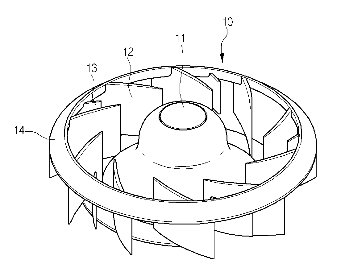
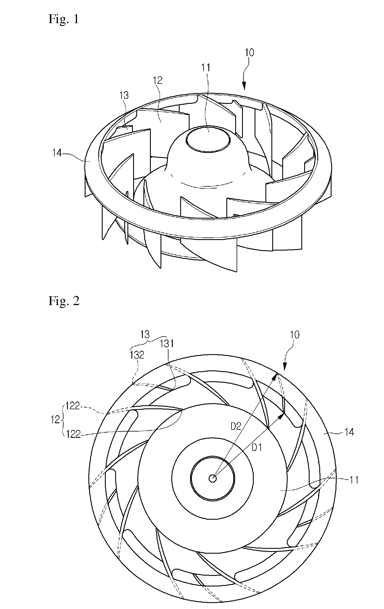
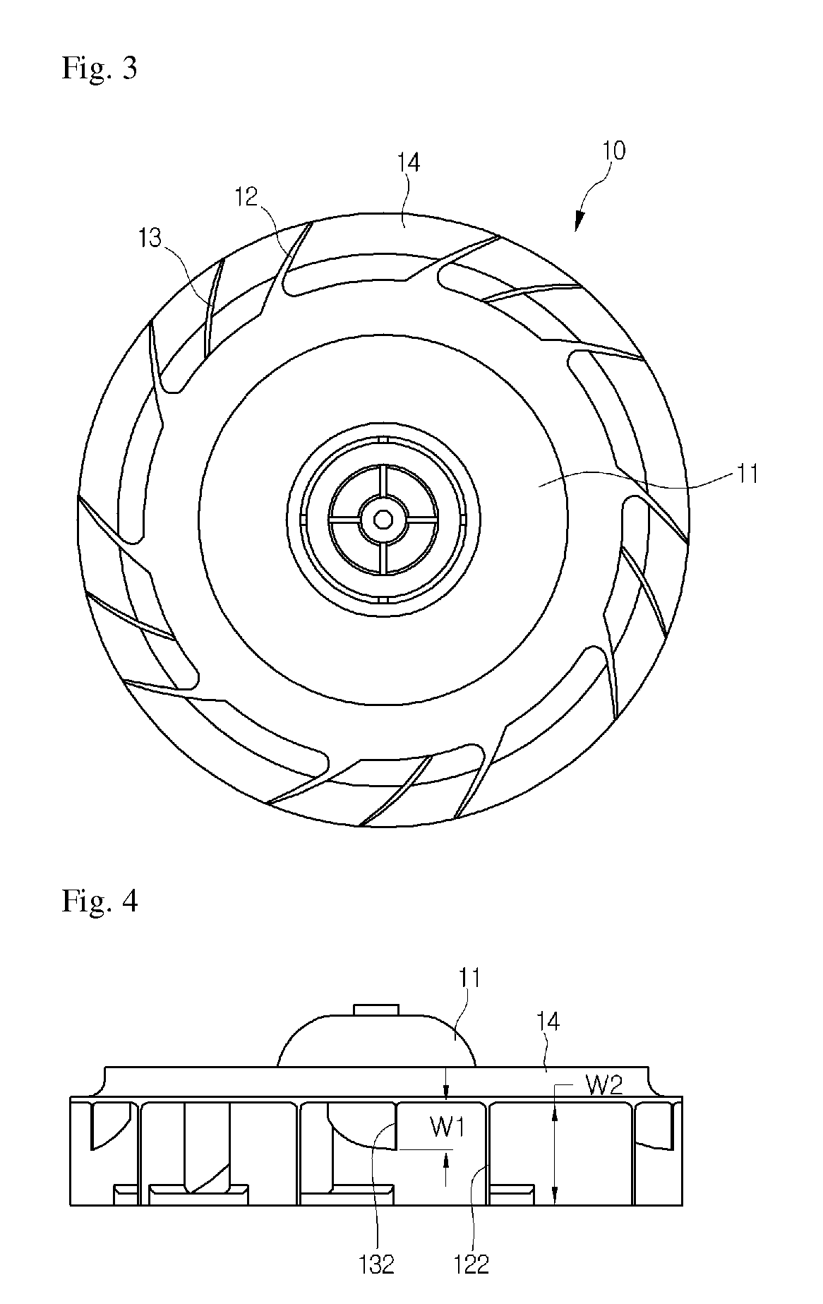
[0012]First, a constant pressure and a flow rate of a fan are increased by installing an auxiliary blade between main blades.
[0013]Second, since the flow rate increases at the same rpm, rpm can decrease while the same flow rate is maintained, and as a result, noise is reduced.
[0014]Third, a velocity distribution of a flow discharged through a trailing edge of the auxiliary blade is substantially uniform, such that a pressure difference between an upper side and a lower side of the trailing edge is minimized, and as a result, a flow property in which the discharged air flows backward is improved.

Problems solved by technology

However, a general centrifugal fan in the related art has disadvantages to be described below.
Therefore, the flow is lost and noise increases and an eddy phenomenon occurs at the upper side of the trailing edge, such that fan efficiency deteriorates.

Method used


Image

  • Centrifugal fan
  • Centrifugal fan
  • Centrifugal fan

Examples


Embodiment Construction

[0021]In the following detailed description of the preferred embodiments, reference is made to the accompanying drawings that form a part hereof, and in which is shown by way of illustration specific preferred embodiments in which the invention may be practiced. These embodiments are described in sufficient detail to enable those skilled in the art to practice the invention, and it is understood that other embodiments may be utilized and that logical structural, mechanical, electrical, and chemical changes may be made without departing from the spirit or scope of the invention. To avoid detail not necessary to enable those skilled in the art to practice the invention, the description may omit certain information known to those skilled in the art. The following detailed description is, therefore, not to be taken in a limiting sense, and the scope of the present invention is defined only by the appended claims.

[0022]Hereinafter, a centrifugal fan according to an exemplary embodiment o...


PUM


Abstract

A centrifugal fan according to an exemplary embodiment of the present invention includes: a hub penetrated by a rotational axis; a plurality of main blades extended in a radial direction from a predetermined point of the top of the hub; a bell mouth formed on a top of the exteriors of the plurality of main blades; and a plurality of auxiliary blades extended in the radial direction between the plurality of main blades, wherein a ratio (D1 / D2) of an inner diameter D1 to an outer diameter D1 of each of the auxiliary blades is in the range of 07 to 0.9.

Description

CROSS REFERENCES RELATED APPLICATIONS[0001]The present application claims the benefits of priority to Korean Patent Application No. 10-2010-0072163 (filed on Jul. 27, 2010), which is herein incorporated by reference in its entirety.THE BACKGROUND[0002]1. The Field[0003]The present invention relates to a centrifugal fan.[0004]2. Description of the Related Art[0005]A centrifugal fan suctions air in an axial direction and discharges the air in a radial direction. The centrifugal fan may be mounted on an evaporation chamber or a machine chamber of an air conditioner and a refrigerator. In particular, in the case of the refrigerator, an area of a cooled air passage is decreased in order to increase a volume in the refrigerator, such that a passage resistance is increased. In order to solve the problem, a centrifugal fan having a high constant pressure property is generally used.[0006]However, a general centrifugal fan in the related art has disadvantages to be described below.[0007]Speci...

Claims


Application Information

Patent Timeline
Patent Type & Authority Applications(United States)
IPC IPC(8): F01D5/22
CPCF04D29/30F04D29/282F04D29/666F04D29/281
Inventor KANG, MYOUNGJUKIM, JINDONGKIM, HOSAN
Owner LG ELECTRONICS INC
Learn More