Electric Storage Module and Electric Storage Device

a technology of electric storage module and battery module, which is applied in the manufacture of final products, cell components, electrochemical generators, etc., can solve the problems inability to achieve high volumetric efficiency for cooling, etc., and achieve the effect of large overall size of battery module and high volumetric efficiency

Active Publication Date: 2012-02-02
HITACHI AUTOMOTIVE SYST LTD
View PDF3 Cites 74 Cited by
  • Summary
  • Abstract
  • Description
  • Claims
  • Application Information

AI Technical Summary

Benefits of technology

[0007]The electric storage module disclosed in the above publication includes a plurality of battery cells connected to one another so as to achieve thermal conduction, are disposed only on one surface of the cooling plate. This means that a high level of volumetric efficiency for cooling cannot be achieved and also, the overall size of the battery module is bound to become large.

Problems solved by technology

This means that a high level of volumetric efficiency for cooling cannot be achieved and also, the overall size of the battery module is bound to become large.

Method used


Image

  • Electric Storage Module and Electric Storage Device
  • Electric Storage Module and Electric Storage Device
  • Electric Storage Module and Electric Storage Device

Examples


embodiment 1

[0053]The following is a description of an electric storage module and an electric storage device according to embodiment 1 of the present invention, given in reference to drawings.

[0054](Electric Storage Module)

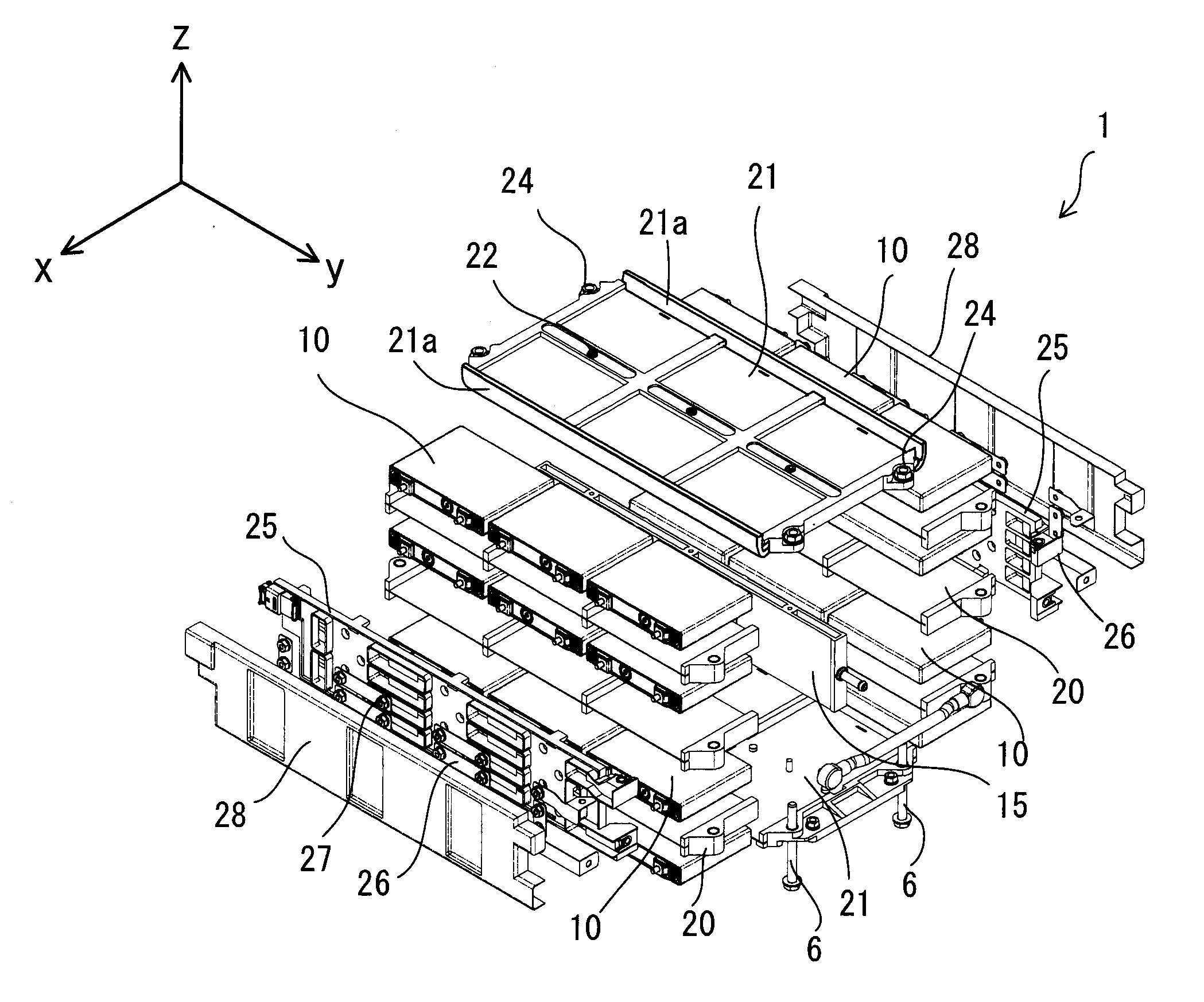
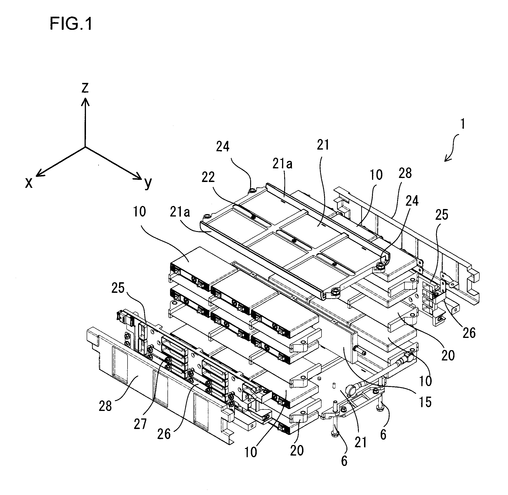
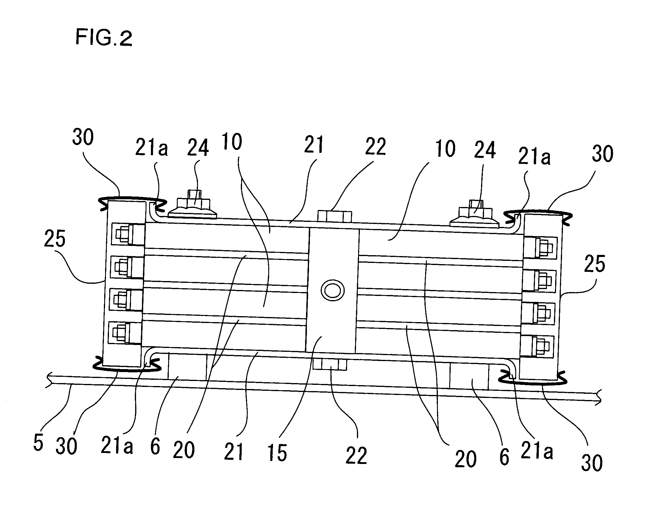
[0055]FIG. 1 is an exploded perspective of an electric storage module (or storage battery module) 1 according to the present invention, and FIG. 2 is a front view of the electric storage module in FIG. 1 taken from the front side of the battery module. FIG. 2 does not include an illustration of a cover 28, which is to be described in detail later.

[0056]The electric storage module 1 includes numerous battery cells 10. As indicated in FIG. 1, the direction extending along the depth of the electric storage module, the direction extending along the length of the electric storage module and the direction extending along the height of the electric storage module are respectively defined as an x direction, a y direction and a z direction. At a substantial center of the electric sto...

embodiment 2

[0102]FIG. 17 is a front view of an electric storage module 1A according to embodiment 2 of the present invention, and FIG. 18 shows the mounting structure with which the cooling plate 15 and the battery cells 10 are mounted in the electric storage module 1A in FIG. 17.

[0103]As shown in FIG. 17, the electric storage module 1A in embodiment 2, unlike the electric storage module in embodiment 1, does not include clips 30. End plates 21A, disposed at the top and the bottom, each extend further forward beyond the front ends of the battery cells 10, with openings 21b formed at the two side edges thereof.

[0104]Holding plates 51, each having a through hole with a diameter greater than that of the openings 21b of the end plates 21A, are disposed on the side where the front ends of the battery cells 10 are located. Collars 23, inserted through the through holes at the holding plates 55, are disposed between the upper and lower end plates 21A. The collars 23 each include a through hole formed...

embodiment 3

[0108]FIGS. 19 through 21 illustrate the electric storage module according to embodiment 3 of the present invention.

[0109]FIG. 19 is a perspective showing the connecting structure with which the cooling plate 15A and the battery cells 10 are connected, FIG. 20 is a plan view of a connecting structure with which the cooling plate 15A and a given battery cell 10 are connected and FIG. 21 is a plan view of the connecting structure with which the cooling plate 15A and three battery cells 10 are connected.

[0110]Recessed portions 15c are formed at the cooling plate 15A over areas thereof that would come into contact with the individual battery cells 10 in embodiment 3. Each recessed portion 15c ranges along the entire height of the cooling plate 15A, with a thermally conductive member 16 housed within the recessed portion 15c. Each battery cell 10 contacts a thermally conductive member 16, with its bottom surface 114B sustaining direct contact with the front surface or the rear surface of...


PUM

PropertyMeasurementUnit
coefficient of thermal conductivityaaaaaaaaaa
compressibilityaaaaaaaaaa
thicknessaaaaaaaaaa

Abstract

An electric storage module includes: a cooling plate with a predetermined thickness between a front surface and a rear surface, with the front surface and the rear surface functioning as cooling surfaces by a coolant flowing in the cooling plate; a first battery row made up with a plurality of battery cells, to be cooled by the cooling plate, arrayed along a predetermined direction, with one end surfaces of the battery cells being coupled with the front surface of the cooling plate so as to achieve thermal conduction; and a second battery row made up with a plurality of battery cells, to be cooled by the cooling plate, arrayed along a predetermined direction, with one end surfaces of the battery cells being coupled with the rear surface of the cooling plate so as to achieve thermal conduction.

Description

INCORPORATION BY REFERENCE[0001]The disclosure of the following priority application is herein incorporated by reference: Japanese Patent Application No. 2010-170029 filed Jul. 29, 2010BACKGROUND OF THE INVENTION[0002]1. Field of the Invention[0003]The present invention relates to an electric storage module and an electric storage device equipped with a plurality of battery cells and capable of discharging and accumulating electrical energy.[0004]2. Description of Related Art[0005]An electric storage module installed as a power source in a hybrid vehicle, an electric vehicle or the like is configured by combining numerous secondary battery cells, such as lithium ion battery cells, nickel-metal-hydride battery cells or nickel cadmium battery cells. Since a very large charging / discharging current flows through the electric storage module, the temperature of the battery cells tends to rise significantly. An increase in the temperature at the battery cells lowers the battery cell perfor...

Claims


Application Information

Patent Timeline
Patent Type & Authority Applications(United States)
IPC IPC(8): H01M10/50H01M2/10H01M10/60H01M10/613H01M10/617H01M10/625H01M10/643H01M10/647H01M10/651H01M10/6551H01M10/6555H01M10/6563H01M10/6568H01M50/209H01M50/213H01M50/264H01M50/271
CPCH01M2/1077H01M10/5004H01M10/5016H01M10/503H01M10/5032H01M10/5075H01M10/504H01M10/5055H01M10/5059H01M10/5067H01M10/5069H01M10/5036H01M10/625H01M10/653H01M10/6563H01M10/647H01M10/6557H01M10/6567H01M10/6555H01M10/643H01M10/6564H01M10/651H01M10/613Y02E60/10Y02P70/50H01M50/271H01M50/209H01M50/213H01M50/264
Inventor AOKI, SADAYUKI
Owner HITACHI AUTOMOTIVE SYST LTD
Why Eureka
Try Eureka