Dc-dc converter

a converter and dc technology, applied in the field of dc-dc converters, can solve problems such as cost increases, and achieve the effect of increasing the error of determined wiring resistan

Active Publication Date: 2012-02-09
ORMON CORP
View PDF2 Cites 14 Cited by
  • Summary
  • Abstract
  • Description
  • Claims
  • Application Information

AI Technical Summary

Benefits of technology

[0022]Therefore, the improper compensation of the voltage drop of the output voltage of the DC-DC converter, caused by the increase in error of the determined wiring resistance, is prevented.
[0023]According to one or more embodiments of the present invention, the voltage drop caused by the wiring resistance can be compensated in the output voltage of the DC-DC converter.

Problems solved by technology

However, when the output voltage is controlled by directly measuring the input voltage of the load of the DC-DC converter, it is necessary to provide the additional wiring connecting the DC-DC converter and the load, and necessary cost increases.

Method used


Image

  • Dc-dc converter
  • Dc-dc converter
  • Dc-dc converter

Examples


first embodiment

1. First Embodiment

[0039]A first embodiment of the present invention will be described with reference to FIGS. 1 to 5.

[0040][Configuration Example of In-Vehicle System 1]

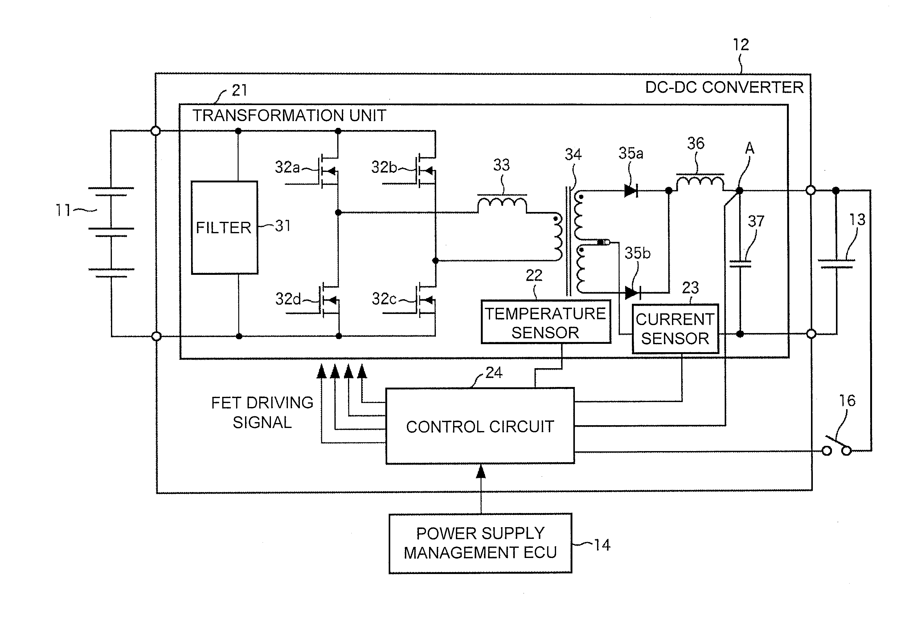
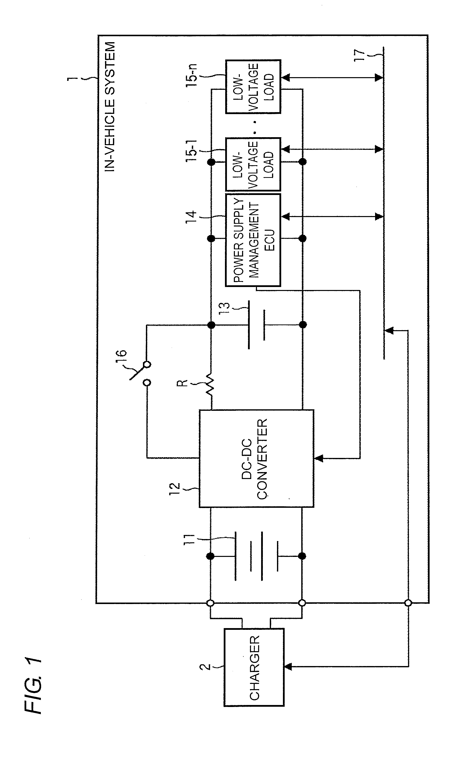
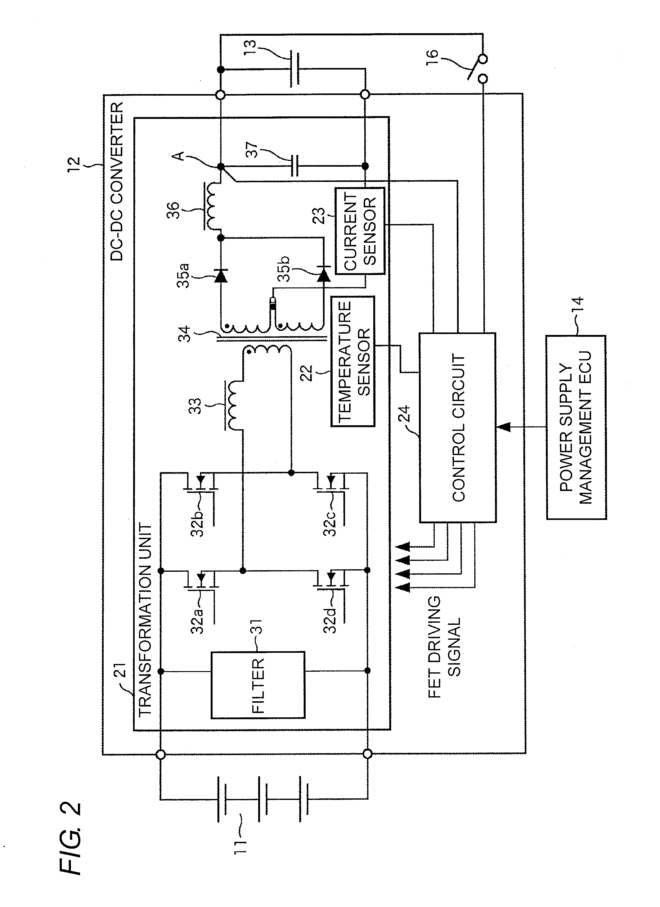
[0041]FIG. 1 is a block diagram illustrating an in-vehicle system according to a first embodiment of the present invention. An in-vehicle system 1 is provided in an electric-powered vehicle such as an EV, an HEV, or a PHEV. The in-vehicle system 1 includes a high-voltage battery 11, a DC-DC converter 12, a low-voltage battery 13, a power-supply management ECU 14, low-voltage loads 15-1 to 15-n, and an ignition switch 16. The power-supply management ECU 14 and the low-voltage loads 15-1 to 15-n are connected to each other through an in-vehicle LAN (Local Area Network) 17, and the power-supply management ECU 14 and the low-voltage loads 15-1 to 15-n transmit and receive various pieces of data by CAN (Controller Area Network) communication.

[0042]The high-voltage battery 11 supplies a DC power having a predetermined vol...

second embodiment

2. Second Embodiment

[0099]A second embodiment of the present invention will be described below with reference to FIGS. 6 to 10.

[0100][Configuration Example of In-Vehicle System 101]

[0101]FIG. 6 is a block diagram illustrating an in-vehicle system of the second embodiment of the present invention. In FIG. 6, the component corresponding to that of FIG. 1 is denoted by the same reference numeral, and the description thereof will not be repeated.

[0102]An in-vehicle system 101 differs from the in-vehicle system 1 of FIG. 1 in that a DC-DC converter 111 is provided instead of the DC-DC converter 12 and that a battery sensor 112 is added. The ignition switch 16 of FIG. 1 is not illustrated in FIG. 6. The power-supply management ECU 14, the low-voltage loads 15-1 to 15-n, the DC-DC converter 111 and the battery sensor 112 are connected to one another through the in-vehicle LAN 17, and transmit and receive various pieces of data by CAN communication.

[0103]The DC-DC converter 111 transforms t...


PUM


Abstract

A voltage drop of an output voltage of a DC-DC converter, caused by a wiring resistance, can properly be compensated at low cost. The DC-DC converter is connected to a low-voltage battery through an ignition switch and started up by the ignition switch. A transformation unit transforms a voltage inputted from a high-voltage battery and supplies the voltage to the low-voltage battery. A control circuit calculates a wiring resistance between the transformation unit and the low-voltage battery based on the voltage inputted from the low-voltage battery through the ignition switch in connecting the ignition switch and an output voltage and an output current of the transformation unit. The control circuit corrects a command value of the output voltage of the transformation unit based on the calculated wiring resistance to control the output voltage of the transformation unit. The invention can be applied to a DC-DC converter for electric-powered vehicle.

Description

CROSS-REFERENCE TO RELATED APPLICATIONS[0001]The present application claims priority from Japanese Patent Application No. 2010-178358, filed Aug. 9, 2010. The contents of both priority applications are hereby incorporated by reference in their entirety.BACKGROUND OF THE INVENTION[0002]1. Technical Field[0003]One or more embodiments of the present invention relate to a DC-DC converter. Particularly, one or more embodiments of the present invention relate to a DC-DC converter that can compensate a voltage drop caused by a wiring resistance.[0004]2. Related Art[0005]Two types of batteries, namely, a high-voltage battery and a low-voltage battery are usually provided in an electric-powered vehicle such as an EV (Electric Vehicle), an HEV (Hybrid Electric Vehicle), or a PHEV (Plug-in Hybrid Electric Vehicle).[0006]The high-voltage battery is mainly used as a power supply for a load of a high voltage (hereinafter, referred to as a high-voltage load), such as a main power motor for driving...

Claims


Application Information

Patent Timeline
Patent Type & Authority Applications(United States)
IPC IPC(8): H02J1/00
CPCH02M2001/0025H02M3/3376B60L1/00B60L53/20H02J7/342H02M1/0025Y02T10/70Y02T10/7072Y02T10/92Y02T90/14Y02T90/12
Inventor IDO, YUSAKUOMOTO, YASUMICHIHACHIYA, KOJI
Owner ORMON CORP
Why Eureka
Try Eureka