
Digital predistortion circuit with extended operating range and a method thereof

a digital predistortion circuit and operating range technology, applied in the field of communication systems, can solve problems such as non-zero delay between, poor overall performance of the system, and inability to solve perfect solutions, and achieve the effects of expanding the range of tx power levels, rapid correction of power amplifier gain, and extended operating rang

Inactive Publication Date: 2012-02-09
ZTE WISTRON TELECOM
View PDF6 Cites 5 Cited by
  • Summary
  • Abstract
  • Description
  • Claims
  • Application Information

AI Technical Summary

Benefits of technology

[0016]An object of the present invention is to provide a digital predistortion circuit with extended operating range, which produces acceptable results for a more expanded range of TX power levels. The digital predistortion circuit comprises: a predistortion function, a D / A converter, a multiplier for performing frequency translation and a power amplifier, the digital predistortion circuit further comprises: a multiplier for receiving a signal to be transmitted and a gain correction factor, multiplying the gain correction factor with the signal to be transmitted and outputting a result of the multiplication to the predistortion function; and a device for calculating the gain correction factor by using a predetermined reference gain and an estimated gain of the power amplifier, and outputting the calculated gain correction factor to the multiplier, whereby a gain of the power amplifier is quickly corrected.
[0027]An object of the present invention is to provide a method for extending an operating range of a digital predistortion circuit, which produces acceptable results for a more expanded range of TX power levels. The method comprises the steps of: calculating a gain correction factor by using a predetermined reference gain and an estimated gain of a power amplifier in the digital predistortion circuit; multiplying the calculated gain correction factor with a signal to be transmitted and outputting a result of the multiplication to a predistortion function in the digital predistortion circuit, whereby a gain of the power amplifier is quickly corrected.

Problems solved by technology

One of the problems with this design is that the PA's characteristics change in time and even small changes in the PA's characteristics can produce a system which has poor overall performance.
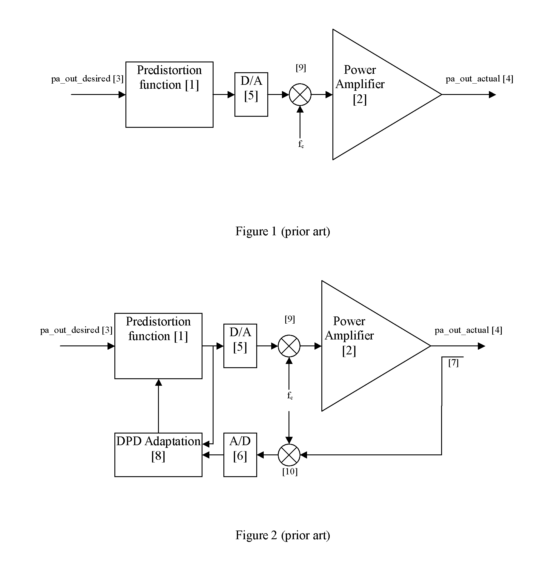
One of the main problems with the DPD implementation as shown in FIG. 2, is that there is a non-zero delay between the time when the characteristics of the PA [2] change and the time when the predistortion module is updated to reflect the new characteristics of the PA [2].
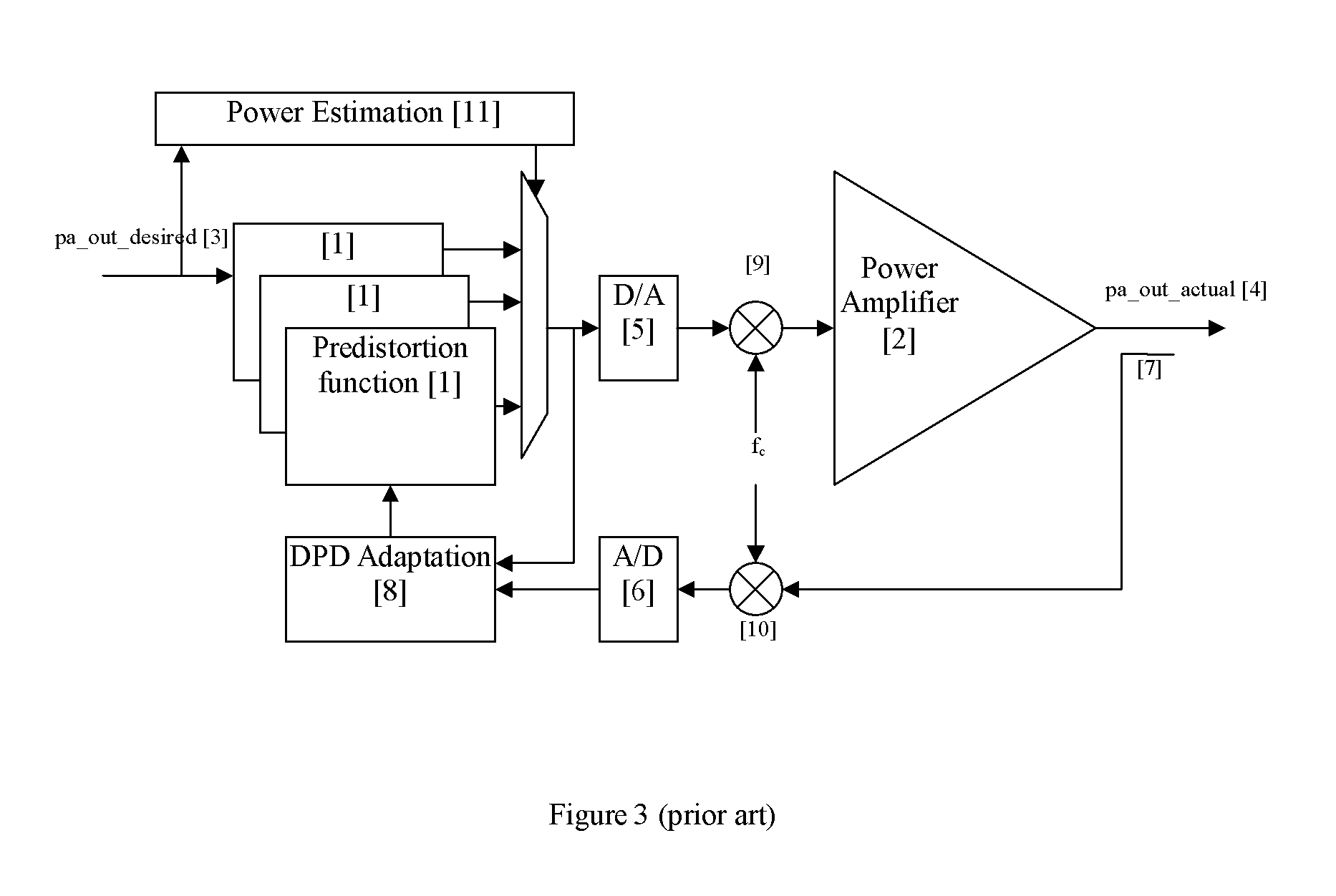
Although the addition of the power estimation module [11] and multiple predistortion functions improves the ability to track the rapid changes in the PA's characteristics, it is not a perfect solution.
Each function needs to be updated in realtime and hence it may take a very long time before all of the predistortion functions are updated.
During the time it takes to update all of the predistortion functions, the PA may be transmitting a poor quality signal.
Furthermore, power estimation errors are possible whereby a wrong predistortion function may be selected.
This will again cause the PA to transmit a poor quality signal.

Method used


Image

  • Digital predistortion circuit with extended operating range and a method thereof
  • Digital predistortion circuit with extended operating range and a method thereof
  • Digital predistortion circuit with extended operating range and a method thereof

Examples


Embodiment Construction

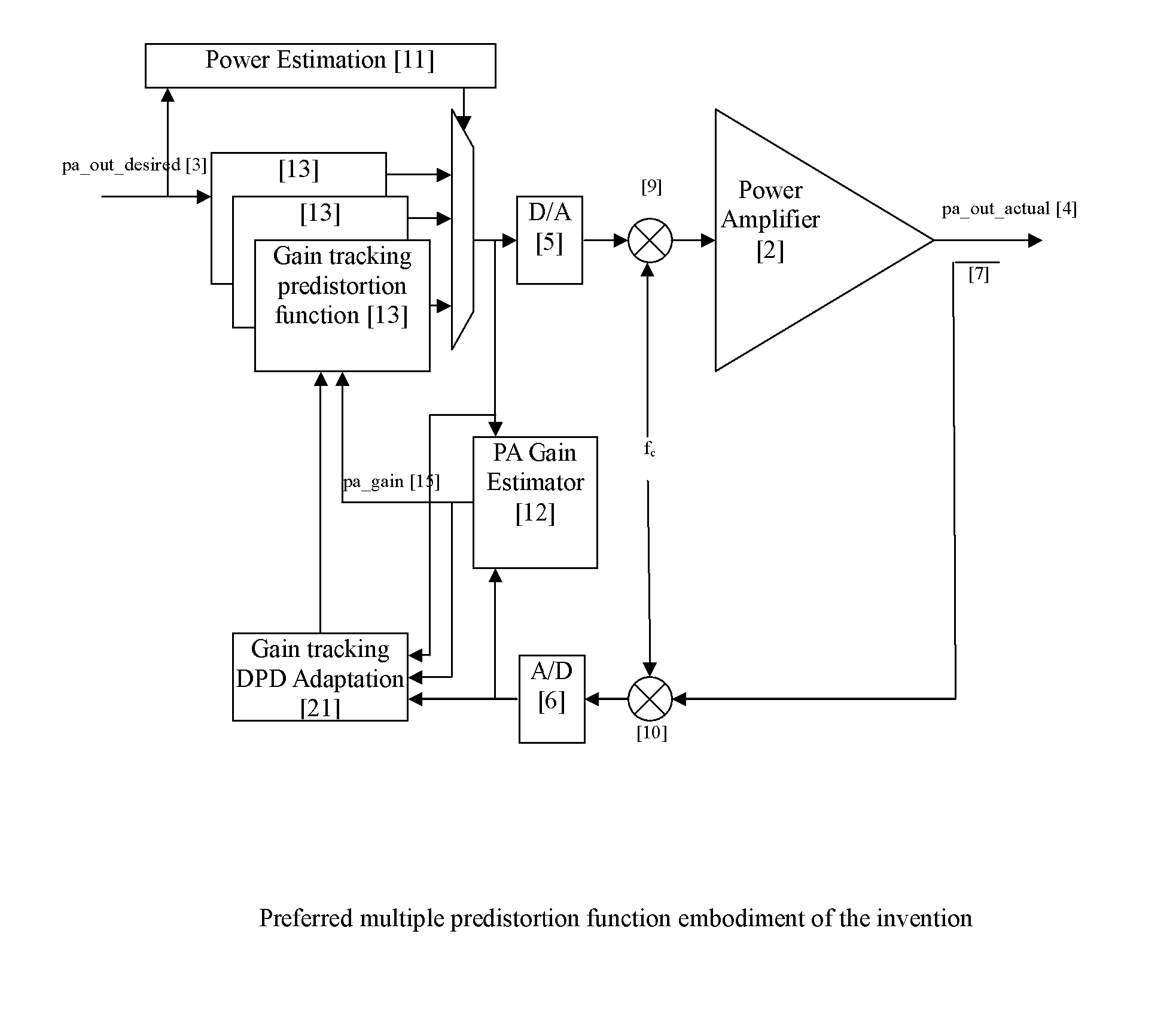
[0046]One embodiment of the invention is depicted in FIG. 4. The signal to be transmitted [3], is sent as an input to a gain tracking predistortion function [13] which uses realtime information about a power amplifier's current gain [15] to create a predistorted signal that is sent to a D / A converter [5]. The power amplifier's current gain [15] comes from a PA gain estimator [12]. The output of the D / A [5] converter is shifted up in frequency by a frequency translator [9] and is then presented to the input of the PA [2].

[0047]A coupler [7] is used to extract a small portion of the PA's output power and forward this signal to a downconverter [10]. The output of the downconverter [10] is sampled by an A / D [6]. The PA gain estimator [12] operates by observing the signal going to the PA [2] and the signal coming from the PA [2], so as to estimate the realtime gain of the PA [2]. One basic method that can be used to estimate the gain of the PA [2] is that the gain estimator [12] can: (1)...


PUM


Abstract

A digital predistortion circuit and method with extended operating range includes a predistortion function, a D / A converter, a multiplier for performing frequency translation and a power amplifier. The digital predistortion circuit includes a multiplier for receiving a signal to be transmitted and a gain correction factor, multiplying the gain correction factor with the signal to be transmitted, and outputting a result of the multiplication to the predistortion function, as well as a device for calculating the gain correction factor by using a predetermined reference gain and an estimated gain of the power amplifier, and outputting the calculated gain correction factor to the multiplier, whereby a gain of the power amplifier is quickly corrected. The digital predistortion circuit and the method thereof produce acceptable results for a more expanded range of TX power levels.

Description

TECHNICAL FIELD[0001]The present invention relates to a communication system, especially to a digital predistortion technique used in a communication system.BACKGROUND[0002]Digital predistortion (DPD) is a technique that is used to improve the efficiency, lower the cost, and improve the transmission quality of a power amplifier (PA) used in a communications system. A typical DPD structure is shown in FIG. 1 where the input signal [3], is passed through a predistortion function [1] to produce a signal that is sent to a digital to analog converter (D / A) [5]. The output of the D / A [5] is sent through a mixer [9] which performs frequency translation to shift the signal up to the desired frequency, and then the signal is amplified by the PA [2]. The general concept is that the predistortion circuit contains a nonlinear inverse model of the nonlinear PA so that when the two nonlinear models are cascaded as shown in the figure, the full cascade can be considered as a linear system. Thus, a...

Claims


Application Information

Patent Timeline
Patent Type & Authority Applications(United States)
IPC IPC(8): H03F1/26
CPCH03F1/3247H03F3/189H04L25/49H03F2200/451H03F3/245
Inventor PEROULAS, JAMESDAI, ZHENGJIAN
Owner ZTE WISTRON TELECOM
Learn More