Position error signal demodulation with target-based blending

a position error and target-based blending technology, applied in the field of disk drives, can solve the problems of limited calibration utility, stitching error, and discontinuity between

Inactive Publication Date: 2012-02-09
KK TOSHIBA
View PDF3 Cites 15 Cited by
  • Summary
  • Abstract
  • Description
  • Claims
  • Application Information

AI Technical Summary

Benefits of technology

[0012]One or more embodiments of the present invention provide a method for servo burst-decoding demodulation in a disk drive that accommodates track pitch variation. Depending on the distance a read head is displaced from a read head target position, a target-based blending scheme, a position-based blending scheme, or a weighted combination of both is used to determine the position of the transducer head. When the transducer head is relatively close to the target position, e.g., within ⅛ of a track, the target-based blending scheme is used to decode servo bursts and calculate the exact head position. When the transducer head is relatively far from the target position, e.g., more than ¼ of a track, the position-based blending scheme is used to decode servo bursts and calculate head position. When the transducer head is an intermediate distance from the target position, a weighted combination of the target-based and position-based blending schemes is used.
[0013]A method of determining positioning errors of a transducer head of a disk drive, according to an embodiment of the invention, comprises the steps of measuring a position error of the transducer head relative to a nominal target position based on servo bursts written on a recording medium of the disk drive and determining a final position error of the transducer head according to one of a first function, a second function, and a third function. The first function is used when the measured position error is less than a first predetermined number. The second function is used when the measured position error is greater than a second predetermined number. The third function is used when the measured position error is between the first and second predetermined numbers. The first predetermined number represents 12.5% of a nominal track width and the second predetermined number represents 25% of the nominal track width.
[0014]A non-transitory computer-readable storage medium, according to an embodiment of the invention, comprises instructions for a processing unit of a disk drive to carry out the steps of measuring a position error of a transducer head of the disk drive relative to a nominal target position based on servo bursts written on a recording medium of the disk drive and determining a final position error of the transducer head according to one of a first function, a second function, and a third function. The first function is used when the measured position error is less than a first predetermined number. The second function is used when the measured position error is greater than a second predetermined number. The third function is used when the measured position error is between the first and second predetermined numbers.
[0015]A disk drive, according to an embodiment of the invention, comprises a transducer head, a recording medium having written thereon servo bursts, and a controller for positioning the transducer head over the recording medium using the servo bursts. The controller is programmed to measure a position error of the transducer head relative to a nominal target position based on the servo bursts and determine a final position error of the transducer head according to one of a first function, a second function, and a third function. The first function is used when the measured position error is less than a first predetermined number. The second function is used when the measured position error is greater than a second predetermined number. The third function is used when the measured position error is between the first and second predetermined numbers.

Problems solved by technology

At ¼ track location (N+0.25), however, both the AB burst pairs and the CD burst pairs provide a strong position signal, and generally there is some discontinuity between these two signals at this transition zone, known as “stitching error.”
Stitched demodulation schemes can be calibrated to accommodate for stitching error that occurs between AB burst pairs and CD burst pairs for nominal track pitch, but because stitching error is greatly exaggerated by track squeeze, such calibration is of limited utility for “squeezed” tracks.
Using stitched demodulation schemes, squeezed tracks generally can have undesirable position error signal (PES) noise, or “chatter” at the ¼ track location, which is known to cause data integrity problems.
When the actual track pitch varies between adjacent or proximate servo sectors, as illustrated between servo sectors k and k+1 in FIG. 1, changes in servo loop gain can cause servo loop stability problems, resulting in unwanted oscillations of read head 160.

Method used


Image

  • Position error signal demodulation with target-based blending
  • Position error signal demodulation with target-based blending
  • Position error signal demodulation with target-based blending

Examples


Embodiment Construction

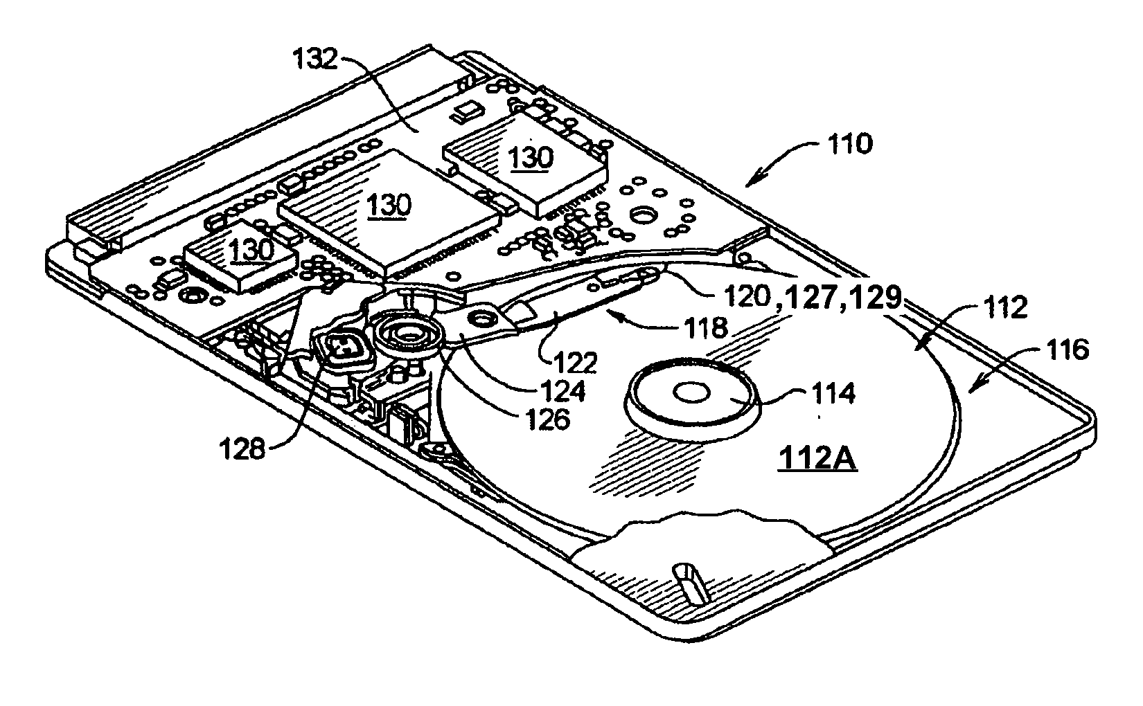
[0027]FIG. 3 is a perspective view of a disk drive 110 that can benefit from embodiments of the invention as described herein. For clarity, disk drive 110 is illustrated without a top cover. Disk drive 110 includes a storage disk 112 that is rotated by a spindle motor 114. Spindle motor 114 is mounted on a base plate 116. An actuator arm assembly 118 is also mounted on base plate 116, and has a slider 120 mounted on a flexure arm 122 with a read head 127 and a write head 129. Flexure arm 122 is attached to an actuator arm 124 that rotates about a bearing assembly 126. Voice coil motor 128 moves slider 120 relative to storage disk 112, thereby positioning read and write heads 127 and 129 over the desired concentric data storage track disposed on the surface 112A of storage disk 112. Spindle motor 114, the read and write heads 127 and 129, and voice coil motor 128 are coupled to electronic circuits 130, which are mounted on a printed circuit board 132. The electronic circuits 130 incl...


PUM

PropertyMeasurementUnit
weightsaaaaaaaaaa
widthaaaaaaaaaa
constant angular velocityaaaaaaaaaa

Abstract

In a disk drive, a method for servo burst-decoding demodulation that accommodates track pitch variation. Depending on the distance a read head is displaced from a read head target position, a target-based blending scheme, a position-based blending scheme, or a weighted combination of both is used to determine the position of the transducer head. When the transducer head is relatively close to the target position, the target-based blending scheme is used to decode servo bursts and calculate the exact head position. When the transducer head is relatively far from the target position, the position-based blending scheme is used to decode servo bursts and calculate head position. When the transducer head is an intermediate distance from the target position, a weighted combination of the target-based and position-based blending schemes is used.

Description

BACKGROUND OF THE INVENTION[0001]1. Field of the Invention[0002]Embodiments of the present invention relate generally to disk drives and, more particularly, to systems and methods for demodulating position error signals in such drives.[0003]2. Description of the Related Art[0004]A disk drive is a data storage device that stores digital data in concentric tracks on the surface of a data storage disk. The data storage disk is a rotatable hard disk with a layer of magnetic material thereon, and data is read from or written to a desired track on the data storage disk using a read / write head that is held proximate to the track while the disk spins about its center at a constant angular velocity.[0005]To properly align the read / write head with a desired track during a read or write operation, disk drives generally use a closed-loop servo system that relies on servo data stored in servo sectors written on the disk surface when the disk drive is manufactured. These servo sectors form “servo...

Claims


Application Information

Patent Timeline
Patent Type & Authority Applications(United States)
IPC IPC(8): G11B27/36
CPCG11B5/59627G11B2220/2516G11B20/10388G11B5/59655
Inventor SZITA, GABOR
Owner KK TOSHIBA
Why Eureka
Try Eureka