Backlight unit

a backlight unit and backlight technology, applied in the field of backlight units, can solve the problems of low luminance, uneven luminance, difficult to remove led-mounted boards in dark environments, etc., and achieve the effect of easy removal of led-mounted boards

Inactive Publication Date: 2012-02-09
JAPAN DISPLAY INC
View PDF7 Cites 18 Cited by
  • Summary
  • Abstract
  • Description
  • Claims
  • Application Information

AI Technical Summary

Benefits of technology

[0021]According to the backlight unit of the present invention, since the protrusion has a slope on which the LED-mounted board slides, to implement the LED-mounted board, the LED-mounted board is to be slide along the slope to automatic...

Problems solved by technology

A reflective type of a liquid crystal display device uses low power consumption since it does not need a backlight, however, the display device becomes hard to see in a dark environment.
On the other hand, backlight sources composed of LEDs have a feature that if a distance to a light receiving su...

Method used


Image

  • Backlight unit
  • Backlight unit
  • Backlight unit

Examples


Embodiment Construction

[0033]Hereinafter, preferred embodiments of the present invention will be described in detail with reference to the embodiments and appended drawings. The following embodiments do not intend to limit the invention to what are described here, but the present invention can be adapted to various modifications within the scope of the appended claims. Note that, the drawings used in this specification for explanation are displayed in different scale size for each layer or member so that each layer or member can fit to a screen so as to be in a perceptible size, and they are not necessarily displayed in proportion as actual size.

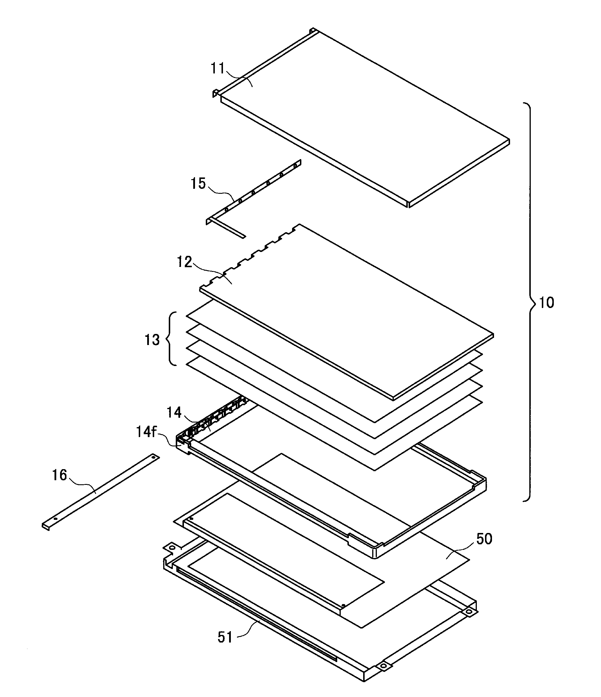
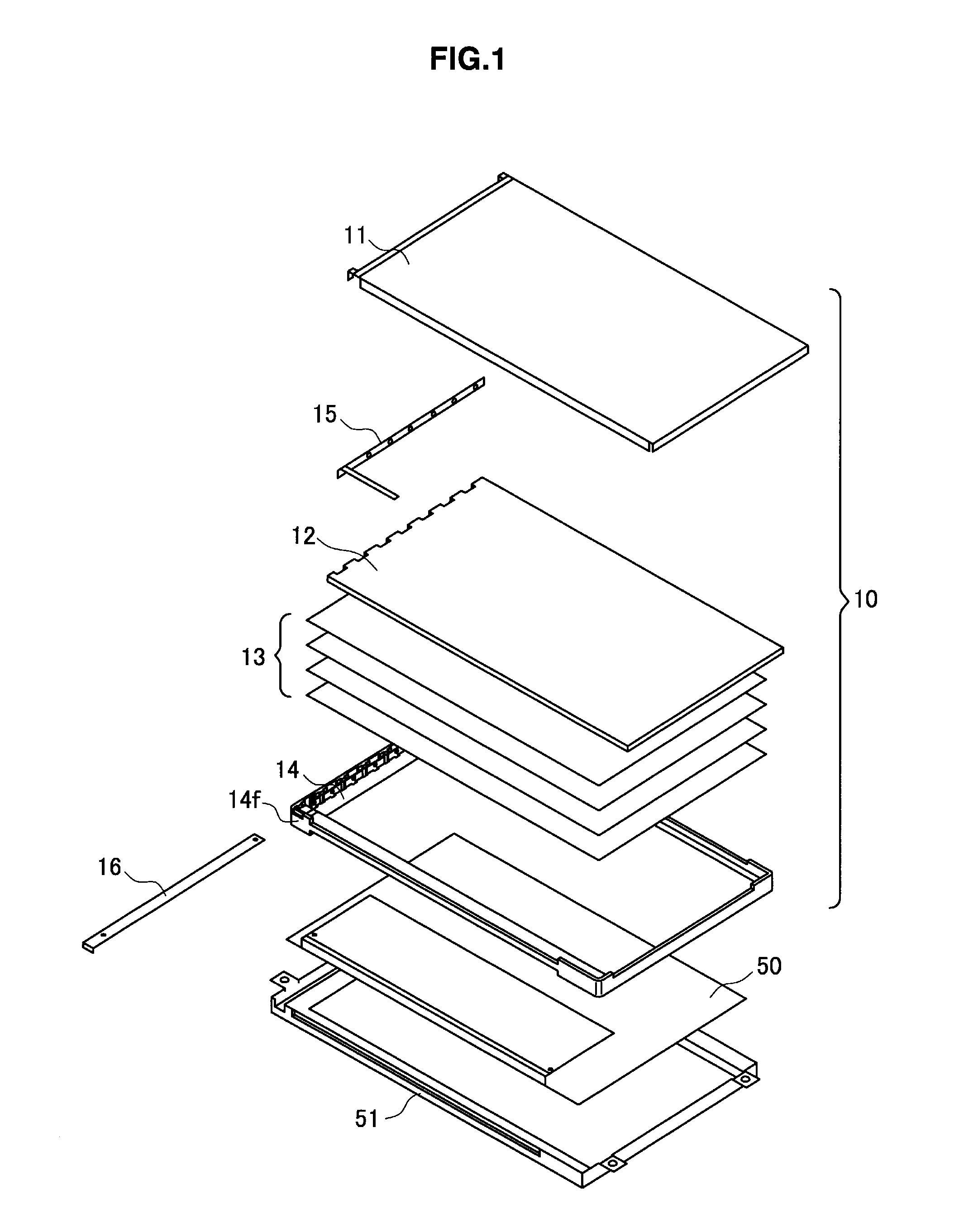
[0034]A liquid crystal display device according to the embodiment of the present invention will be explained with reference to FIG. 1 to FIG. 10. A backlight unit 10 that is used for the liquid crystal display device of the present embodiment is, as shown in FIG. 10, arranged on a back surface of a liquid crystal panel 50 which is transmissive or semi-transmissive...


PUM


Abstract

Provided is a device including a backlight unit including a LED-mounted board having LEDs as a backlight source, a light guide plate to which the LEDs are disposed to face, and which has a light receiving surface to which light from the LEDs incidents and an emission surface from which the incident light is output, and a frame which holds the light guide plate. The frame 14 has a protrusion for positioning which engages the LED-mounted board.

Description

TECHNICAL FIELD[0001]The present invention relates to a backlight unit using light-emitting diodes (hereinafter, referred to as LEDs) as a backlight source, more specifically, it relates to a backlight unit that enables a LED-mounted board with LEDs as a backlight source fixed on a substrate to be exchangeable, and that enables positioning of the LED-mounted board to be done correctly so as to suppress unevenness of luminance and variation in luminance between before and after replacing.BACKGROUND ART[0002]A liquid crystal display device is used for displaying in many electronic devices due to its features such as being light, thin, and low power consumption comparing to a CRT (cathod-ray tube). The liquid crystal display device is to change a direction of liquid crystal molecules aligned in a certain direction by an electric field, and to display images by changing light transmittance of a liquid crystal layer. As the method of displaying by the liquid crystal display device, there...

Claims


Application Information

Patent Timeline
IPC IPC(8): G09F13/08
CPCG02B6/0086G02B6/0021
Inventor HASHINO, NARUO
Owner JAPAN DISPLAY INC
Why Eureka
Try Eureka