Method and system for the small-scale production of liquified natural gas (LNG) and cold compressed gas (CCNG) from low-pressure natural gas

a low-pressure natural gas and liquefied gas technology, applied in the field of gas liquefaction, can solve the problems of increasing no commercially viable small-scale liquefied natural gas production facilities anywhere in the world, and the cost of lng to the end user is not high enough, so as to achieve the effect of reducing the cost of production and reducing the cost of large-scale production

Inactive Publication Date: 2012-02-16
VANDOR DAVID
View PDF4 Cites 67 Cited by
  • Summary
  • Abstract
  • Description
  • Claims
  • Application Information

AI Technical Summary

Benefits of technology

[0009]The disclosed invention relates to a system for the small-scale production of liquid natural gas comprising: a natural gas supply, the natural gas supply being at a pressure in a range of about 55 psia to about 350 psia; a prime mover in fluid communication with the natural gas supply, and in fluid communication with a third heat exchanger; a multi-stage compressor in operational communication with the prime mover; the multi-stage compressor comprising at least a first stage compressor, a second stage compressor, and a third stage compressor, and where the inlet temperature of fluid entering the first stage compressor is less than about 40° F., and where the inlet temperature of fluid entering the second stage compressor is less than about 40° F.; a first inter-cooler in fluid communication with the first stage compressor; a molecular sieve in fluid communication with the first inter-cooler and in fluid communication with the natural gas supply; a fourth heat exchanger in fluid communication with the molecular sieve and in fluid communication with the first stage compressor; a second inter-cooler in fluid communication with the second stage compressor; a first heat exchanger in fluid communication with the second inter-cooler and in fluid communication with the third stage compressor; an after-cooler in fluid communication with the third stage compressor; a second heat exchanger in fluid communication with the after-cooler; a main heat exchanger in fluid communication with the second heat exchanger, in fluid communication with a phase separator, in fluid communication with a gas turbo-expander, and in fluid communication with the fourth heat exchanger, where the operational flow rate from the main heat exchanger to the gas turbo-expander can be as low as about 1,450 lb/hr during continuous operation; a first expansion device in fluid communication with the main heat exchanger; a sub-cooling heat exchanger in fluid communication with the first expansion valve;a second expansion device in fluid communication with the sub-cooling heat exchanger; a pressure tank in fluid communication with the second expansion valve; a four-way valve in fluid communication with the pressure tank; the four-way valve in fluid communication with the sub-cooling heat exchanger and in fluid communication with the main heat exchanger;the gas turbo-expander in fluid communication with the phase separator, and in operational communication with an expander driven compressor; the expander driven compressor in fluid communication with a fifth heat exchanger; the fifth heat exchanger in fluid communication with second stage compressor; an ammonia absorption chiller in fluid communication with the prime mover, in fluid communication with the first heat exchanger, in fluid communication with the second heat exchanger, in fluid communication with the third heat exchanger, and in fluid communication with a cooling tower; a make-up water line in fluid communication with the cooling tower; and where the amount of liquid natural gas produced by this system while continuously running during a 24 hour day can be as low as about 6,000 liters per day, where the system has no more than two expansion valves; and where the first and second devices are selected from a group consisting of a compressor-loaded multi-phase expander turbine, and an expansion valve.
[0010]The invention also relates to a system for the small-scale production of cold compressed natural gas comprising: a natural gas supply, the natural gas having a pressure in a range of about 55 psia to about 350 psia; a prime mover in fluid communication with the natural gas supply, and in fluid communication with a third heat exchanger; a multi-stage compressor in operational communication with the prime mover; the multi-stage compressor comprising a first stage compressor, a second stage compressor, and a third stage compressor, and where the inlet temperature of fluid entering the first stage compressor is less than about 40° F., and where the inlet temperature of fluid entering subsequent stages of the compressor is less than 40° F.; a first inter-cooler in fluid communication with the first stage compressor and with a waste heat driven chiller; a molecular sieve in fluid communication with the first inter-cooler and in fluid communication with the natural gas supply; a fourth heat exchanger in fluid communication with the molecular sieve and in fluid communication with the first stage compressor; a second inter-cooler in fluid communication with a waste heat driven chiller and the second stage compressor; a first heat exchanger in fluid communication with the second in

Problems solved by technology

There are no commercially viable Small-Scale liquefied natural gas (“LNG”) production facilities anywhere in the world.
The use of tanker trucks or terminals increases the cost of the LNG to the end user, because the delivered price must include the substantial cost of transporting the LNG from the production or import location to the customer.
Those transportation costs tend to outweigh the lower production costs of large-scale LNG manufacture, where there is a large distance between the LNG source and the customer.
More generally, the standard model for CNG production and dispensing (in the absence of an on-site LNG source) requires large compressors that produce the CNG on demand, because CNG is not dense enough to allow for any practical way to store it in advance of its dispensing to vehicles.
Thus, all CNG stations operate on a “just in time” production basis, without the ability to produce and store CNG during off-peak periods.
The cost of “just in time” production is higher because it often includes peak period “demand charges” for the electricity used to run the oversized compressors.
Such tanks produce “boil off” which is generally vented to the atmosphere, causing methane emissions and loss of product, further increasing the net cost of the LNG, to both the end user and (by way of the emissions) to society at large.
Heat gain to the storage tank, in the absence

Method used


Image

  • Method and system for the small-scale production of liquified natural gas (LNG) and cold compressed gas (CCNG) from low-pressure natural gas
  • Method and system for the small-scale production of liquified natural gas (LNG) and cold compressed gas (CCNG) from low-pressure natural gas
  • Method and system for the small-scale production of liquified natural gas (LNG) and cold compressed gas (CCNG) from low-pressure natural gas

Examples


Embodiment Construction

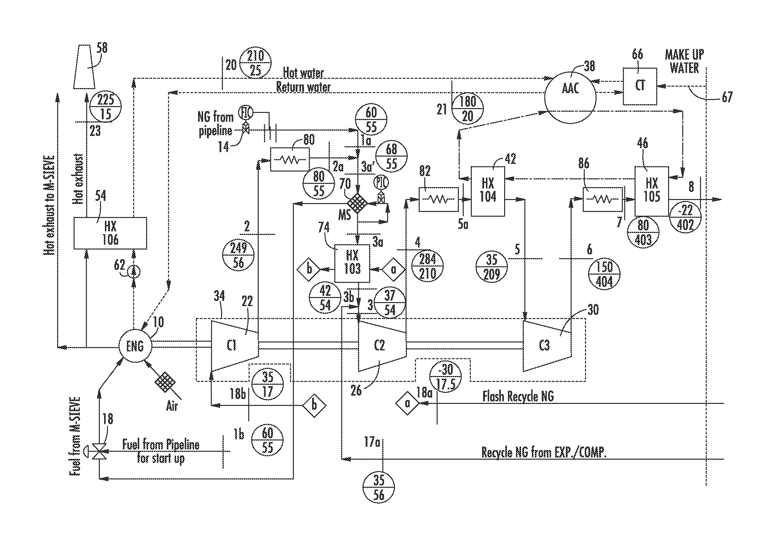
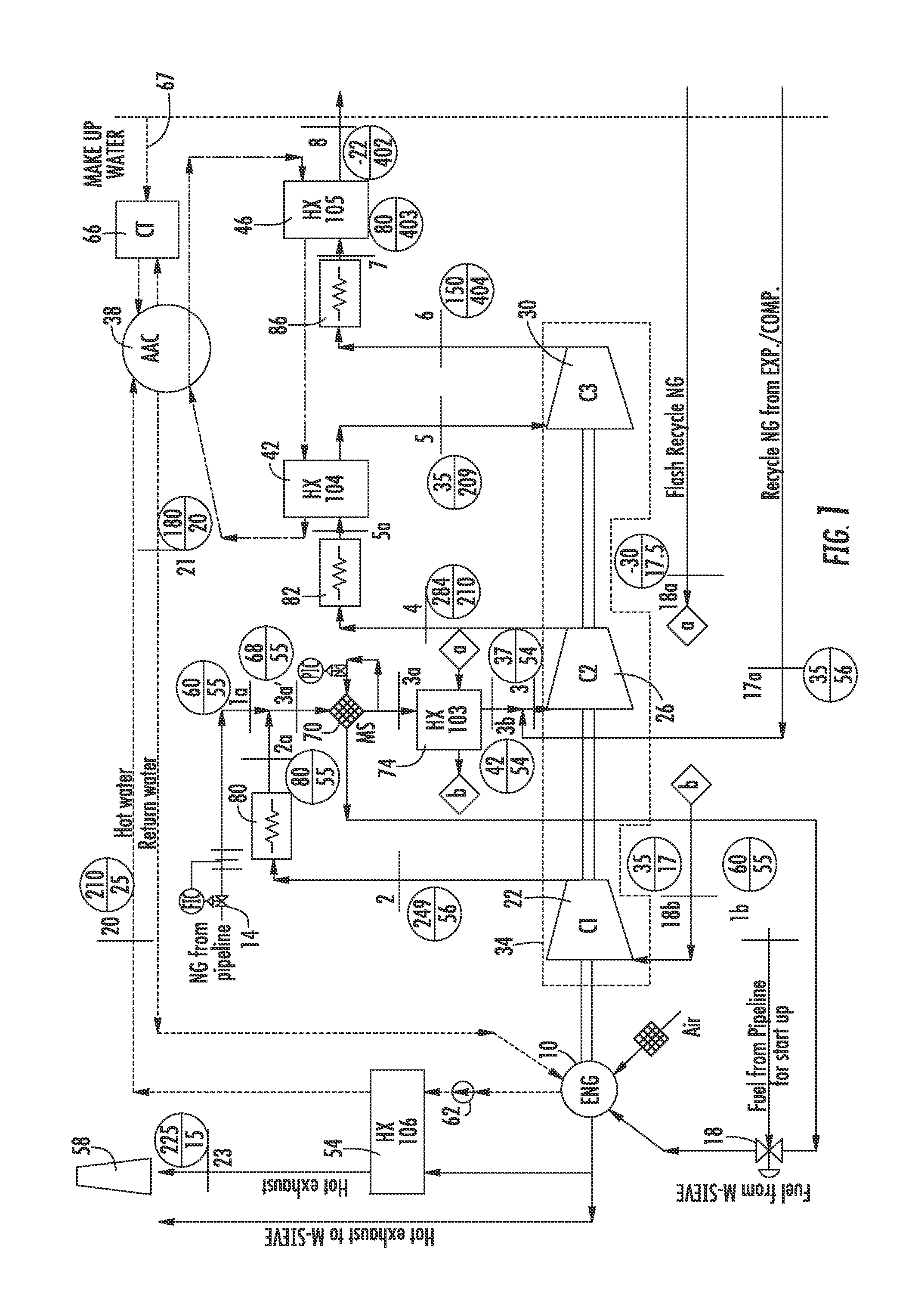
[0024]The disclosed process provides a means to produce, at small-scales, LNG at or near the vehicles that will be served by the facility. With on-site liquefaction inherent in the disclosed process, the LNG product need not be as cold as the LNG produced at distant, large-scale production plants. “Warmer” LNG requires less energy input than colder LNG, and LNG made at (or near) the vehicle fleet it serves will require less energy input for transporting the product. Similarly, if the main customer base is CNG vehicles, then the LNG used to dispense CNG (that system being known as L / CNG) need not be any colder than required for adequately storing and pumping the LNG to the pressure needed for CNG dispensing.

[0025]The inventor, who is an expert in this field, is not aware of any existing, commercially viable Small-Scale LNG plants anywhere in the world and is not aware of any CCNG production, storage or dispensing systems or of a CNG dispensing systems that includes CCNG production an...


PUM


Abstract

A system for the production of LNG from low-pressure feed gas sources, at small production scales and at lower energy input costs. A system for the small-scale production of cold compressed natural gas (CCNG). A method of dispensing natural gas from stored CCNG, comprising: dispensing CCNG from a CCNG storage tank; pumping the CCNG by a cryogenic liquid pump to a pressure suitable for compressed natural gas dispensing and storage in on-vehicle compressed natural gas storage tanks; recovering cold from the CCNG by heat exchange with natural gas feeding the natural gas production plant to replace dispensed product. A system for the storage, transport, and dispensing of natural gas, comprising: means for handling natural gas in a CCNG state where the natural gas is a non-liquid, but is dense-enough to allow for pumping to pressure by a cryogenic liquid pump.

Description

CROSS-REFERENCES[0001]This patent application is a continuation-in-part of patent application Ser. No. 11 / 934,845 by David Vandor, entitled “Method and System for the Small-scale Production of Liquefied Natural Gas (LNG) from Low-pressure Gas”, filed on Nov. 5, 2007, the entire contents of which are fully incorporated by reference herein.TECHNICAL FIELD[0002]The present invention relates generally to the compression, refrigeration and liquefaction of gases, and more particularly to the liquefaction of a gas, such as natural gas, on a small scale.BACKGROUND[0003]There are no commercially viable Small-Scale liquefied natural gas (“LNG”) production facilities anywhere in the world. “Small-Scale” means less than about 10,000 liters / day. Thus, any existing liquefied natural gas-fueled fleet must depend on deliveries by tanker truck from larger-scale LNG plants or from LNG import terminals. The use of tanker trucks or terminals increases the cost of the LNG to the end user, because the de...

Claims


Application Information

Patent Timeline
IPC IPC(8): F25J1/00F17C13/00F17C7/00
CPCF25J1/0022F25J1/0037F25J1/004F25J1/0042F25J1/0045F25J1/0202F25J1/0227F25J1/023F25J1/0231F25J1/0242F25J1/0245F25J1/0254F25J1/0281F25J1/0283F25J1/0284F25J1/0288F25J2230/04F25J2230/22F25J2230/30F25J2235/60F25J2245/02F25J2245/90F25J2270/906F25J2290/62
Inventor VANDOR, DAVID
Owner VANDOR DAVID
Why Eureka
Try Eureka