Low-energy waste gas cooling using direct contact condenser

a direct contact condenser and waste gas technology, applied in the field of cooling process liquid systems and methods, can solve the problems of not being suitable for direct use in the treatment step, and achieve the effects of reducing the duty of refrigeration, reducing the cost, and increasing the availability

Active Publication Date: 2015-03-24
FLUOR TECH CORP
View PDF19 Cites 0 Cited by
  • Summary
  • Abstract
  • Description
  • Claims
  • Application Information

AI Technical Summary

Benefits of technology

[0010]In especially preferred aspects of waste gas cooling, refrigeration duty is significantly reduced by splitting the direct contact bed into two distinct sections having individual direct contact beds wherein one section receives cooled process liquid from a first cooling device (e.g., air cooler), and wherein another section receives cooled process liquid from a second cooling device (e.g., cooler with external refrigerant). Most preferably, first and second cooling devices are distinct such that the first cooling device operates with a first coolant, the second cooling device operates with a second coolant, wherein the first coolant has a lower cost and / or a higher availability that the second coolant.

Problems solved by technology

In this context, it should be noted that many waste gases are formed at relatively high temperatures (e.g., at 150° F., or higher) from a waste gas source such as a heater or a turbine, and are therefore not suitable for direct use in the treatment step to remove the undesired component(s).

Method used


Image

  • Low-energy waste gas cooling using direct contact condenser
  • Low-energy waste gas cooling using direct contact condenser
  • Low-energy waste gas cooling using direct contact condenser

Examples


Embodiment Construction

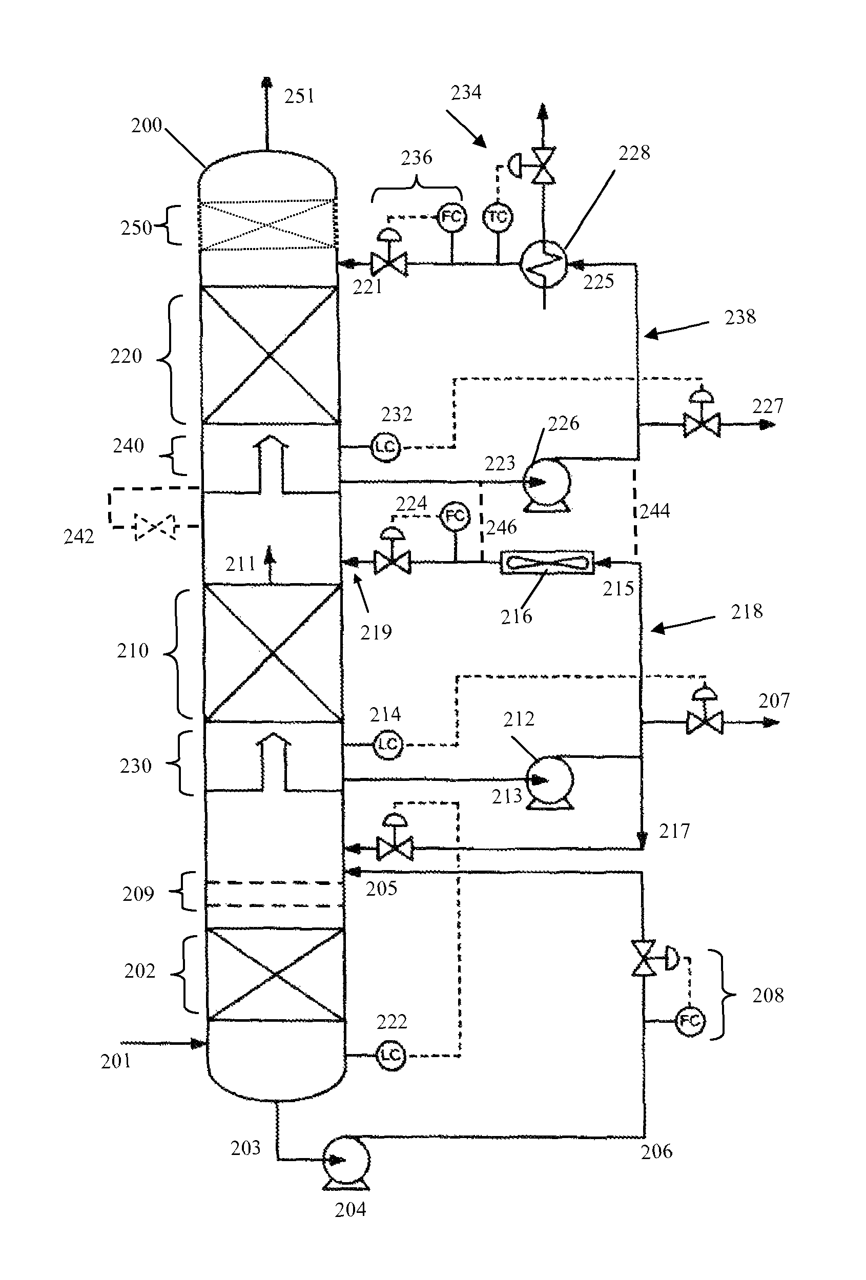
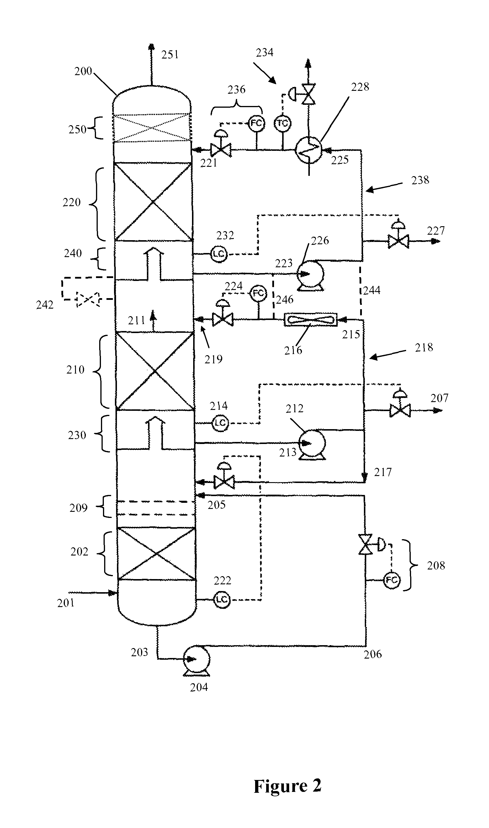
[0021]The inventors have discovered that external refrigeration can be minimized by splitting each of the direct-contact section and the pumparound circuit into two sections. Preferred configurations provide for an air-cooled bottom pumparound circuit and a top pumparound circuit that uses water or other non-air refrigerant. Viewed from a different perspective, it should therefore be appreciated that one cooling device operates with a coolant that is less expensive and / or has higher availability, while the other cooling device operate with distinct coolant. Thus, for example, by decoupling the pumparound circuits, some of the refrigeration duty normally required of the cooling device using external refrigerant can be shifted to the air cooler. Because of the cost difference between air and other refrigerants, such shift results in significant cost-savings.

[0022]Additionally, splitting the pumparound circuit allows for the circulation rate at each section to be increased (instead of ...


PUM

PropertyMeasurementUnit
temperatureaaaaaaaaaa

Abstract

Heat is removed from a process liquid of a direct contact condenser in waste gas cooling using two separate and distinct cooling devices that provide cooled process liquid to at least two separate sections in the direct contact condenser. Most preferably, the sections are liquidly isolated and provide the heated process liquids to the respective cooling devices. However, in other embodiments, the sections are liquidly coupled to each other so to allow transfer of the process liquid from one section to another section. One of the two cooling devices uses a lower-cost or higher-availability coolant that the other. It is generally preferred that one of the cooling devices is an air cooler and that another one of the cooling devices employs a cooling medium other than air.

Description

[0001]This application is a US national phase based on International Patent Application PCT / US2009 / 052569, which was filed Aug. 3, 2009.FIELD OF THE INVENTION[0002]The field of the invention is systems and methods of cooling process liquids, especially as it relates to cooling process water in direct contact condensers (DCC) for cooling tail gas in sulfur recovery plants.BACKGROUND[0003]In most common sulfur recovery plants, tails gas from a sulfur recovery unit is cooled by countercurrent heat exchange with a process liquid (typically water) in a DCC tower that includes a heat exchange section having a packed bed, a grid, trays, angle irons, or combination thereof to improve heat transfer. Hot gas rising through the packed bed cools down as it contacts the descending cooler process liquid, which is heated in turn by the hot gas. As the gas cools, condensable vapor condenses out of the gas, which further heats the process fluid. The heated process liquid is then collected at the bot...

Claims


Application Information

Patent Timeline
Patent Type & Authority Patents(United States)
IPC IPC(8): B01D47/12B01D47/06B01D53/18B01D47/14B01F3/04B01D5/00C01B17/04
CPCC01B17/0456B01D5/003
Inventor KISTER, HENRYNIELSEN, RICHARD B.
Owner FLUOR TECH CORP
Why Eureka
Try Eureka