Method and device for operating an internal combustion engine having a compressor for compressing the air supplied to the internal combustion engine

a technology of internal combustion engine and compressor, which is applied in the direction of combustion engines, machines/engines, electric control, etc., can solve the problems of error being able to be detected during the closing of the clutch, and achieve the effect of increasing the reliability of diagnosis, increasing diagnosis reliability, and increasing diagnostic reliability

Inactive Publication Date: 2012-02-16
ROBERT BOSCH GMBH
View PDF12 Cites 9 Cited by
  • Summary
  • Abstract
  • Description
  • Claims
  • Application Information

AI Technical Summary

Benefits of technology

[0005]By contrast, the method according to the present invention and the device according to the present invention have the advantage that a first value of the variable characterizing the air mass flow, before the switching on of the compressor by closing the clutch, is compared to a second value of the variable characterizing the air mass flow after the switching on of the compressor by closing the clutch, and an error is detected as a function of a deviation of the first value of the first variable characterizing the air mass flow from the second value of the variable characterizing the air mass flow. In this manner one is able to diagnose whether the clutch is closing correctly. Consequently, a diagnosis of the clutch of the compressor is enabled, which does not require any additional sensor system.
[0006]It is of advantage if the second value of the variable characterizing the air mass flow is ascertained after the expiration of a specified time since the closing of the clutch. This increases the reliability of the diagnosis, since, as a rule, after closing the clutch so as to engage the compressor, the air mass flow will not change abruptly but steadily.
[0007]It is also advantageous that an error is detected if the second value of the variable characterizing the air mass flow exceeds the first variable characterizing the air mass flow by less than a first specified threshold value. In this way the reliability of the diagnosis is also increased, and it is prevented that measuring inaccuracies and tolerances, during the ascertainment of the first value of the variable characterizing the air mass flow and the second value of the variable characterizing the air mass flow, corrupt the diagnostic result.

Problems solved by technology

In this case, an error is able to be detected during the closing of the clutch, for turning on the compressor, especially simply and rapidly, and without a further threshold value comparison.

Method used


Image

  • Method and device for operating an internal combustion engine having a compressor for compressing the air supplied to the internal combustion engine
  • Method and device for operating an internal combustion engine having a compressor for compressing the air supplied to the internal combustion engine
  • Method and device for operating an internal combustion engine having a compressor for compressing the air supplied to the internal combustion engine

Examples


Embodiment Construction

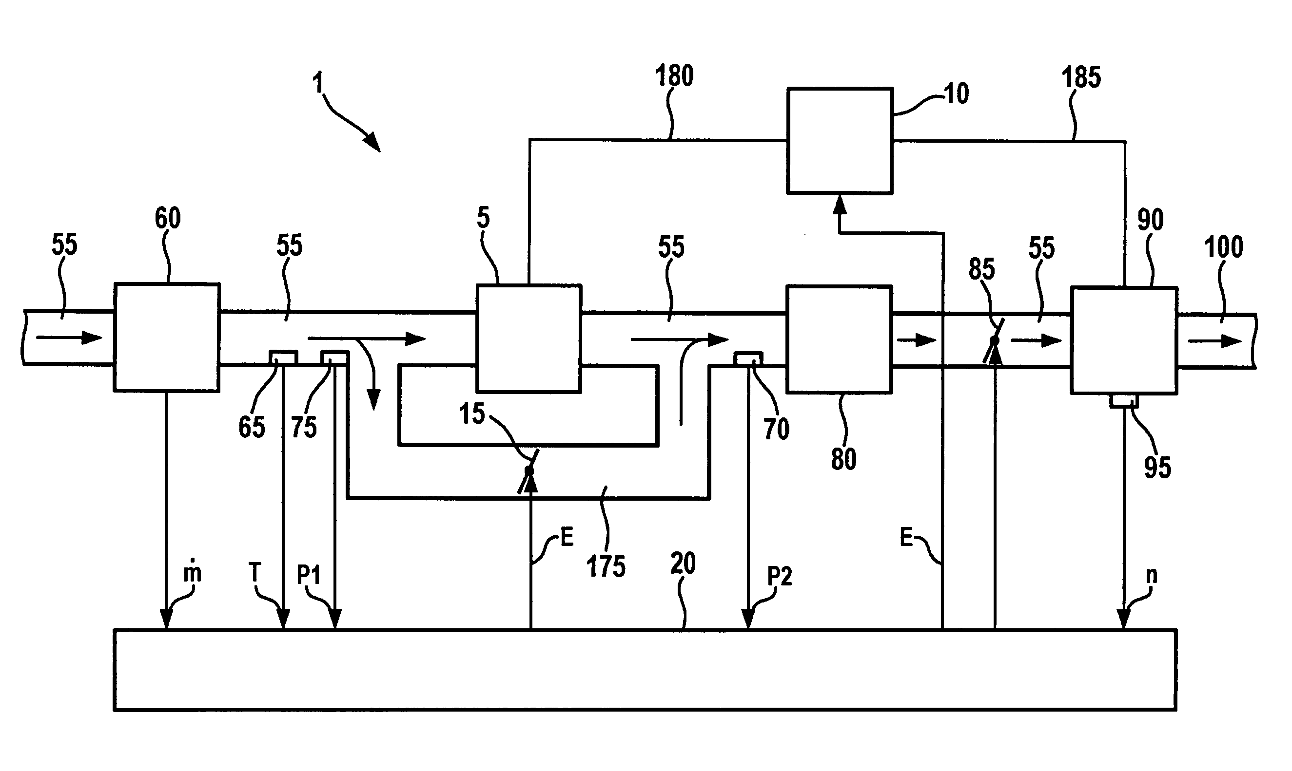
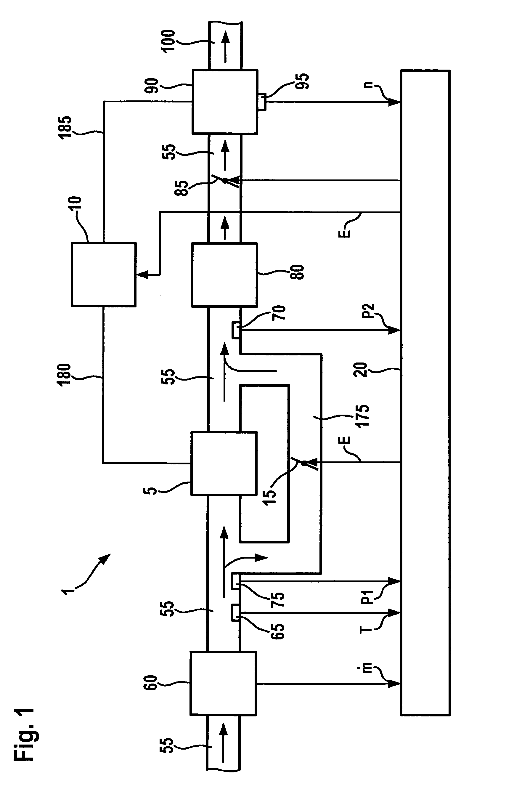
[0016]In FIG. 1, reference numeral 1 denotes an internal combustion engine, which may be developed as an Otto engine or a Diesel engine. Fresh air is supplied via an air supply 55 to a combustion chamber of an engine block 90 of internal combustion engine 1, having one or more cylinders that are not shown in FIG. 1. The flow direction of the fresh air in air supply 55 is indicated by arrows in FIG. 1. A throttle valve 85 is situated in air supply 55. The air mass flow to the combustion chamber of engine block 90 is influenced by the degree of opening of throttle valve 85. The degree of opening of throttle valve 85 is set by a control unit 20. The setting of the degree of opening of throttle valve 85, for example, is a function of a power requirement on internal combustion engine 1, in this instance. The power requirement may be derived, for instance, from the degree of operation of an accelerator, in the case in which the internal combustion engine 1 is driving a vehicle. The power ...


PUM


Abstract

In a method for operating an internal combustion engine having a compressor, the diagnosing of a clutch of the compressor is achieved without an additional sensor system. The compressor is turned on via the clutch, and a variable characterizing the air-mass flow to the internal combustion engine is ascertained. A first value of the variable characterizing the air mass flow before turning on the compressor is compared to a second value of the variable characterizing the air mass flow after turning on the compressor by closing the clutch, and an error is detected as a function of a deviation between the first value and the second value of the variable characterizing the air mass flow.

Description

BACKGROUND OF THE INVENTION[0001]1. Field of the Invention[0002]The present invention relates to a method and a device for operating an internal combustion engine having a compressor for compressing the air supplied to the internal combustion engine.[0003]2. Description of Related Art[0004]An internal combustion engine having a compressor is known from published German patent application document DE 10 2006 061 567 Al, the compressor being able to be connected to the crankshaft of the internal combustion engine via a clutch. A throttle valve is situated upstream of an injector in an intake manifold, in this instance, and upstream of this, in turn, an HFM sensor, which records the air mass flowing through the intake manifold.BRIEF SUMMARY OF THE INVENTION[0005]By contrast, the method according to the present invention and the device according to the present invention have the advantage that a first value of the variable characterizing the air mass flow, before the switching on of the...

Claims


Application Information

Patent Timeline
Patent Type & Authority Applications(United States)
IPC IPC(8): F02B33/00
CPCF02B33/34F02B39/12F02B39/16F02D41/0007F02D41/18F02D41/221F02D2200/0402Y02T10/40Y02T10/144Y02T10/12F02D23/005
Inventor HEINKELE, MATTHIASMENOLD, PATRICKDRUNG, MICHAEL
Owner ROBERT BOSCH GMBH
Why Eureka
Try Eureka