Vehicular Air Conditioning System

Active Publication Date: 2012-02-16
HITACHI LTD
View PDF4 Cites 41 Cited by
  • Summary
  • Abstract
  • Description
  • Claims
  • Application Information

AI Technical Summary

Benefits of technology

[0021]According to the present invention it is possible to provide a vehicular air con

Problems solved by technology

In case of performing both heating unit cooling and room cooling at a time using a refrigerating cycle, the prior art involves the problem that the cooling medium temperature cannot always be controlled to a temperature appropriate for both air conditioning load and heating unit, because the prior art is of the construction in which the same cooling medium is supplied to both heating unit and heat exchanger for air conditioning.
Thus, there has been the inconvenience that the power consumption in the refrig

Method used


Image

  • Vehicular Air Conditioning System
  • Vehicular Air Conditioning System
  • Vehicular Air Conditioning System

Examples


Example

[0044]The following description is now provided about a vehicular air conditioning system according to an embodiment of the present invention which is applied to an electric car. The present invention is applicable not only to electric cars but also to motor-driven vehicles such as hybrid cars, electric railroads and construction vehicles.

[0045]In the following embodiment reference will be made as an example to an AC motor driven by an inverter, but in the present invention no limitation is made to the AC motor and the invention is applicable to all kinds of rotating electric machines (motor-generators), including DC motors driven by a converter such as, for example, thyristor leonard devices, and pulse motors driven by a chopper power supply.

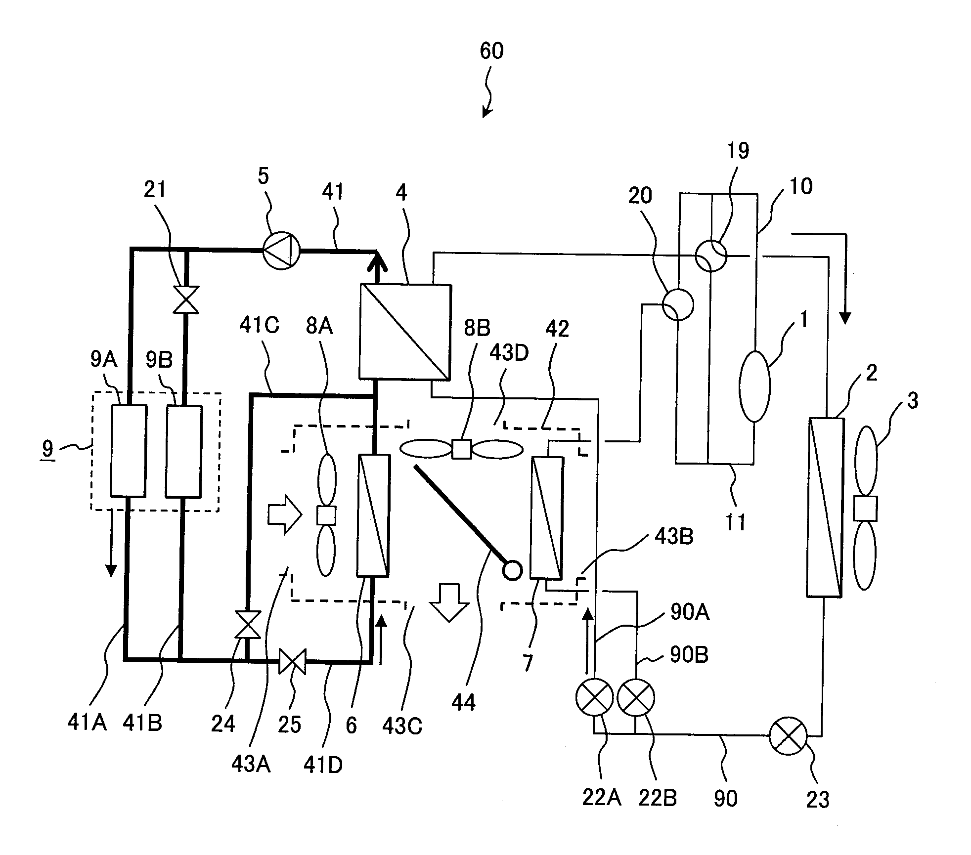
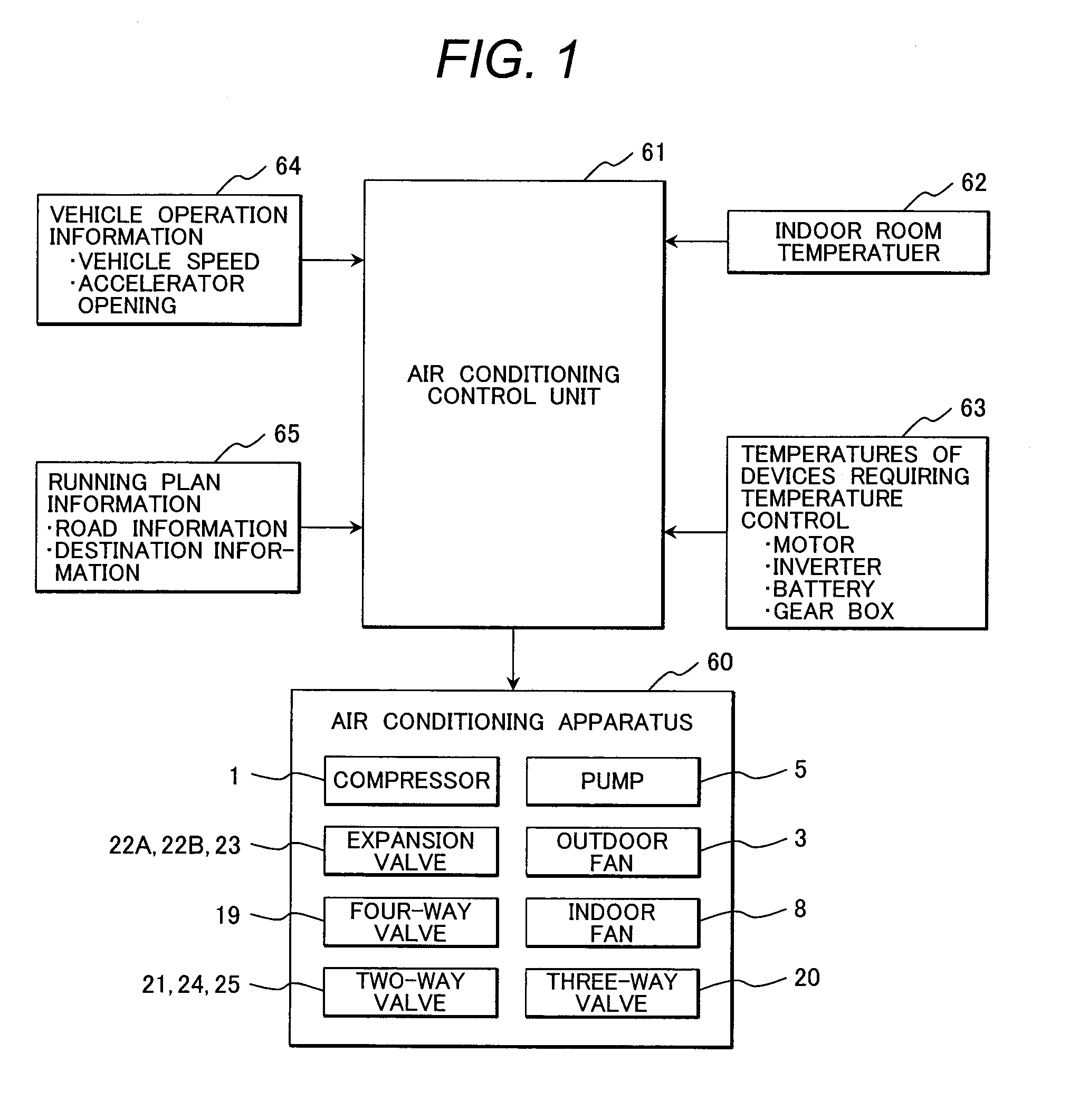
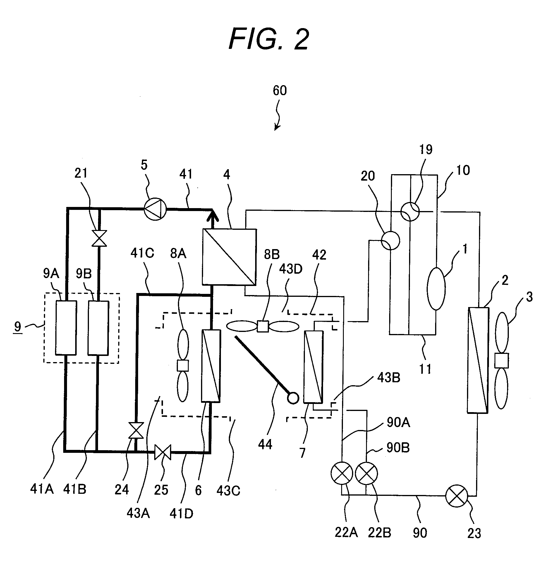
[0046]FIG. 1 is a diagram showing a schematic construction of a vehicular air conditioning system embodying the present invention. The vehicular air conditioning system shown in FIG. 1 includes an air conditioning apparatus 60 to perform coolin...


PUM


Abstract

A vehicular air conditioning system capable of suppressing the power consumption of a refrigerating cycle is disclosed. The vehicular air conditioning system comprises a refrigerating cycle circuit comprising a compressor, an outside heat exchanger and an inside air conditioning heat exchanger annularly connected in order, and a device cooling circuit comprising a heating unit, an inside cooling heat exchanger, an intermediate heat exchanger and a pump being annularly connected, the intermediate heat exchanger being constructed such that one end of a piping of the cooling medium for air conditioning is connected to a liquid piping, the liquid piping providing connection between the outside heat exchanger and the inside air conditioning heat exchanger, and an opposite end of the piping of the cooling medium for air conditioning is connected to a suction port of the compressor.

Description

CLAIM OF PRIORITY[0001]The present application claims priority from Japanese Patent Application No. 2010-179925 filed on Aug. 11, 2010, the content of which is hereby incorporated by reference into this application.BACKGROUND OF THE INVENTION[0002]1. Field of the Invention[0003]The present invention relates to a vehicular air conditioning system.[0004]2. Description of the Related Art[0005]A system is known which utilizes the heat generated from a heating unit such as, for example, an inverter circuit mounted on a vehicle for air conditioning.[0006]For example, in Japanese Patent No. 4285292 (Patent Document 1), in connection with a refrigerating cycle apparatus having a cooling circuit for cooling an in-vehicle heating unit with a cooling medium which is circulated by a cooling medium circulating pump and also having an evaporator which absorbs heat from the cooling medium present in the cooling circuit, there is disclosed a technique related to a method for operating a vehicular c...

Claims


Application Information

Patent Timeline
IPC IPC(8): F24F7/00B60H1/32B60H1/00
CPCB60H1/00021Y02T10/7005B60H1/00385B60H1/00907B60H2001/00178B60H2001/00307B60H2001/00928B60H2001/00935B60H2001/00949B60L50/51B60L50/52B60L58/26B60L58/27B60L3/0061B60L1/003B60L1/02B60L3/003B60L2200/40B60L2240/12B60L2240/34B60L2240/36B60L2240/545B60L2250/26B60L2200/26Y02T10/705B60H1/00278Y02T10/70
Inventor OSAKA, TADASHIMATSUSHIMA, HIROAKISEKIYA, SACHIOIMANISHI, YUTO
Owner HITACHI LTD
Why Eureka
Try Eureka