Method of manufacturing antenna using sintering of metal and antenna manufactured by the same

a technology of metal sintering and manufacturing method, which is applied in the direction of resonant antennas, waveguide type devices, printed electric components, etc., can solve the problems of relatively low productivity, relatively high manufacturing cost, and inconvenient three-dimensional antenna manufacturing method, so as to prevent the influence of metal plating process on health and environmen

Inactive Publication Date: 2012-02-16
DYNATRON
View PDF2 Cites 144 Cited by
  • Summary
  • Abstract
  • Description
  • Claims
  • Application Information

AI Technical Summary

Benefits of technology

[0024]Furthermore, a metal plating process may be omitted so that bad influence

Problems solved by technology

The thermal bonding method may be not proper to an antenna having a three-dimensional shape or a complex shape.
The thermal bonding method has a lot of processes so that productivity may be relatively low and manufacturing cost may be relatively high.
Defect rate of the double injection process may be relati

Method used


Image

  • Method of manufacturing antenna using sintering of metal and antenna manufactured by the same
  • Method of manufacturing antenna using sintering of metal and antenna manufactured by the same
  • Method of manufacturing antenna using sintering of metal and antenna manufactured by the same

Examples


Embodiment Construction

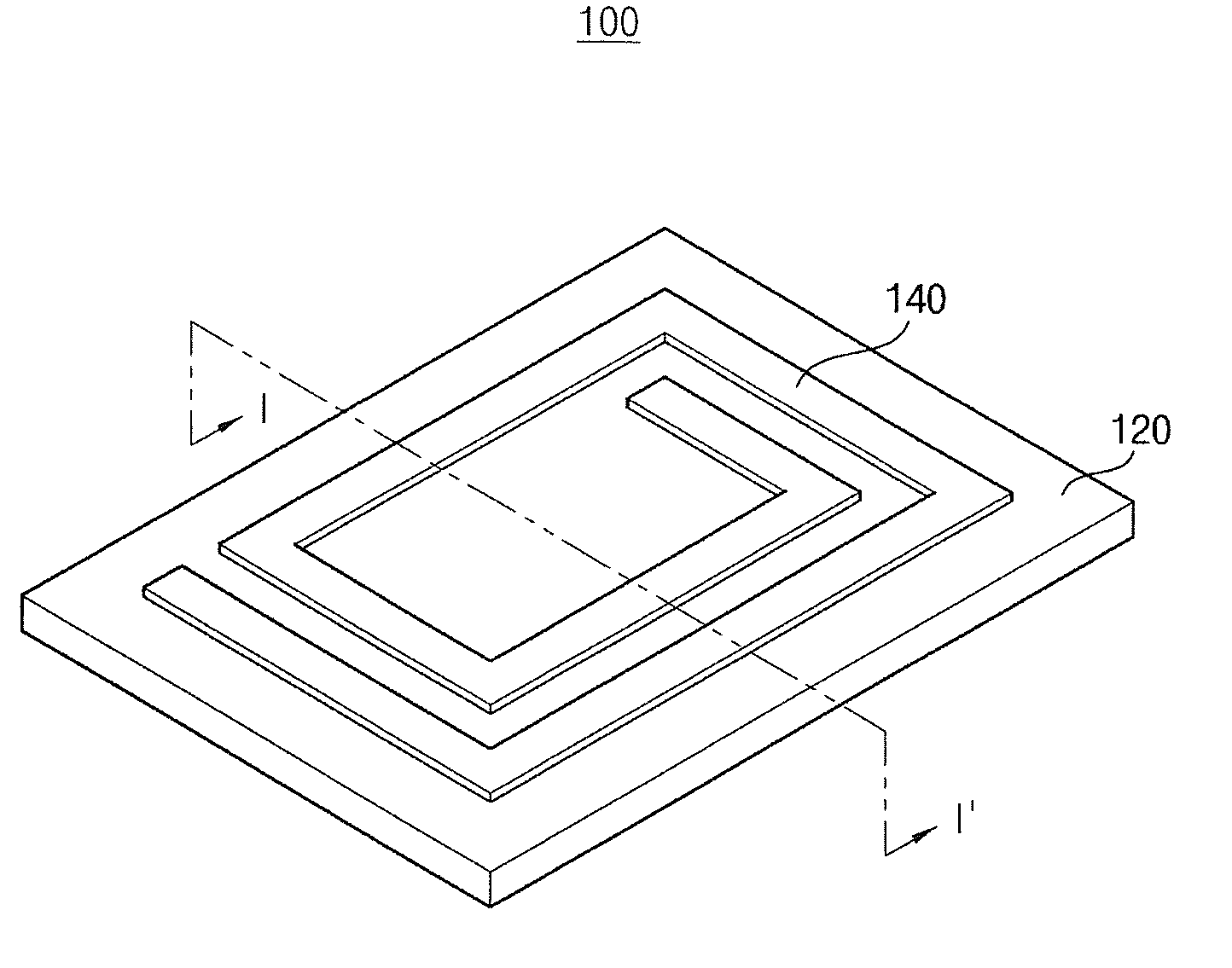
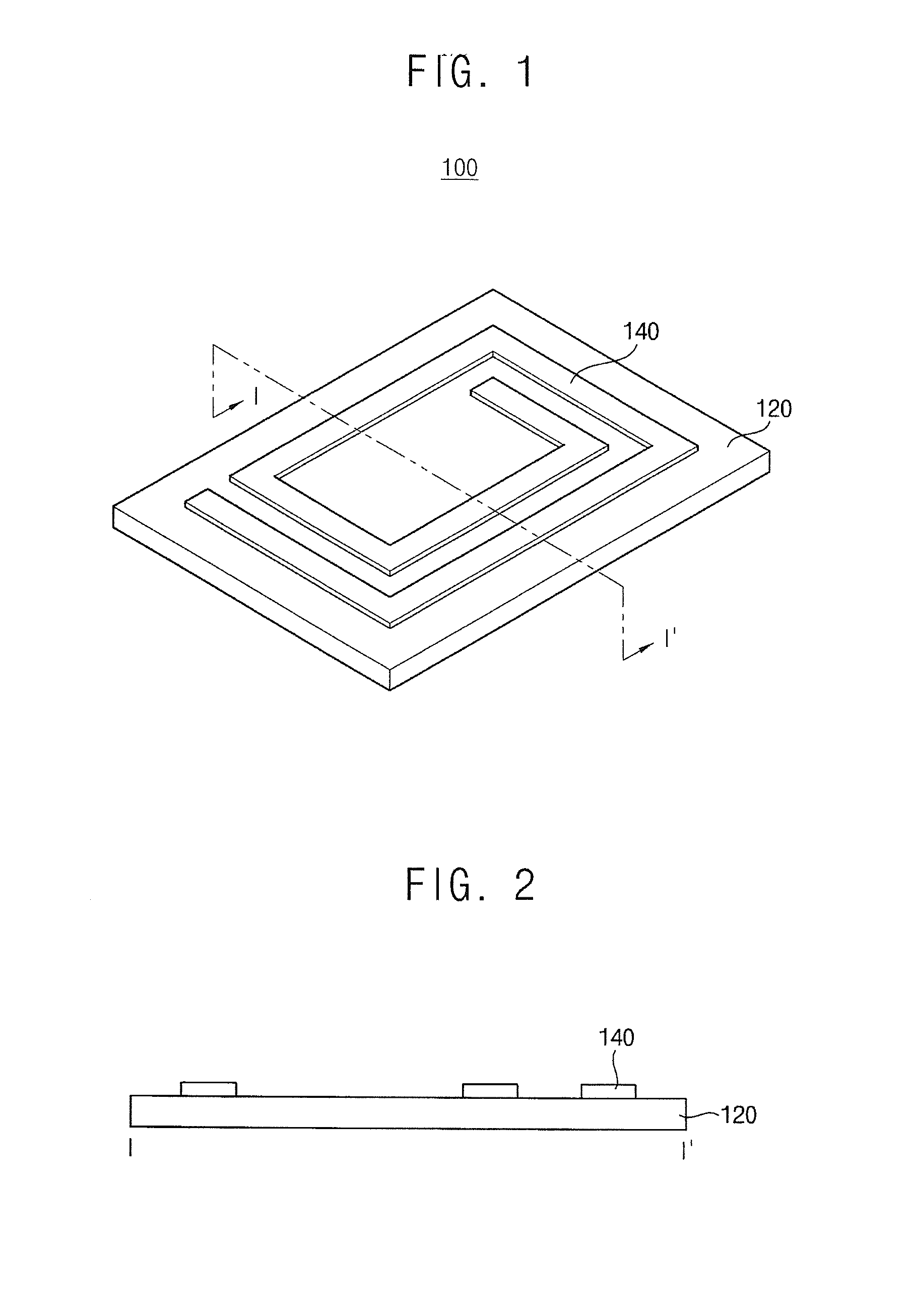
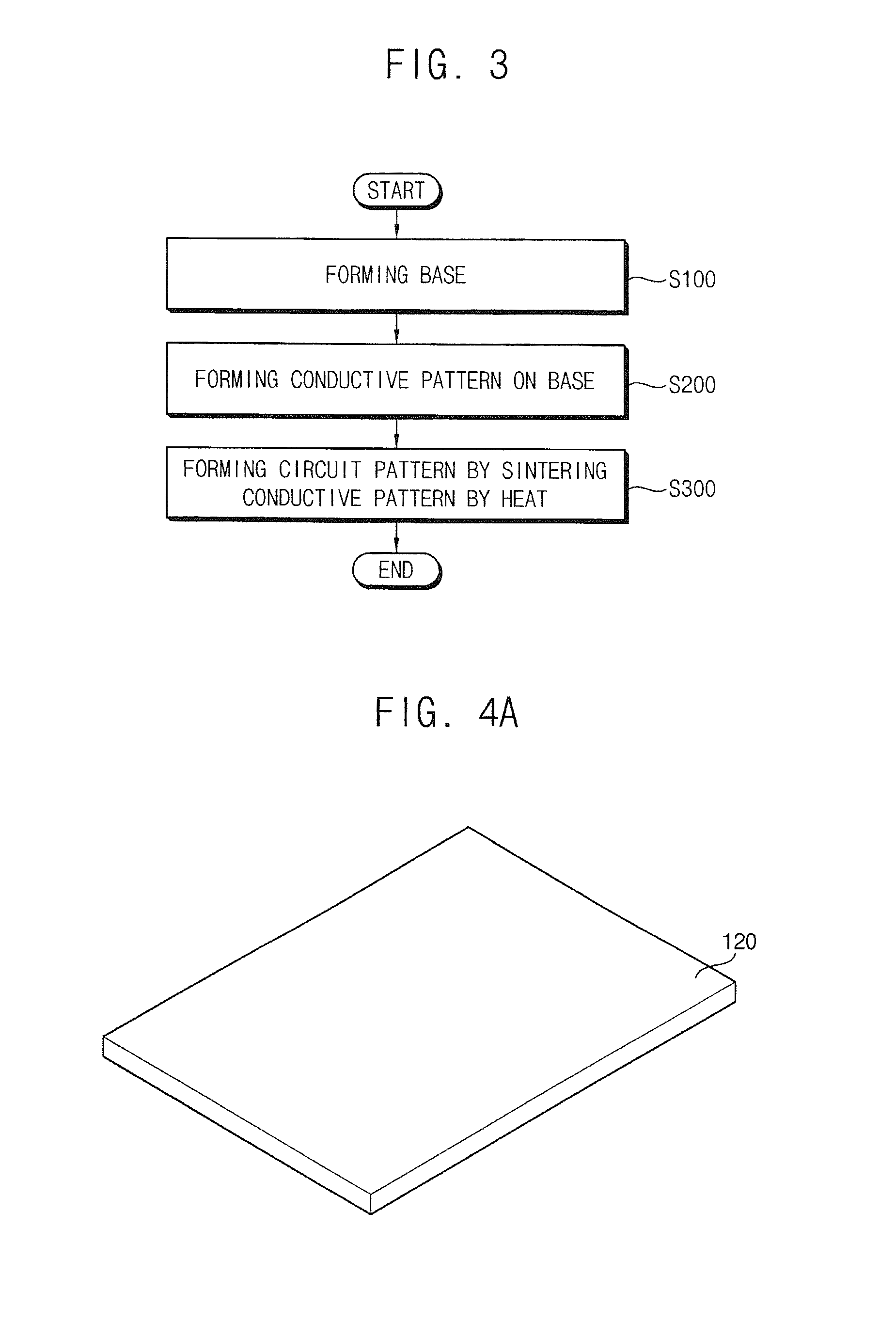
[0032]The present invention is described more fully hereinafter with reference to the accompanying drawings, in which example embodiments of the present invention are shown. The present invention may, however, be embodied in many different forms and should not be construed as limited to the example embodiments set forth herein. Rather, these example embodiments are provided so that this disclosure will be thorough and complete, and will fully convey the scope of the present invention to those skilled in the art. In the drawings, the sizes and relative sizes of layers and regions may be exaggerated for clarity.

[0033]It will be understood that when an element or layer is referred to as being “on,”“connected to” or “coupled to” another element or layer, it can be directly on, connected or coupled to the other element or layer or intervening elements or layers may be present. In contrast, when an element is referred to as being “directly on,”“directly connected to” or “directly coupled ...


PUM

PropertyMeasurementUnit
Sizeaaaaaaaaaa
Sizeaaaaaaaaaa
Temperatureaaaaaaaaaa

Abstract

A method of manufacturing an antenna includes forming a base including a synthetic resin, forming a conductive pattern on the base and forming a circuit pattern by sintering the conductive pattern by applying heat. The conductive pattern includes a conductive paste and a binding material binding the base and the conductive pattern. The conductive paste includes a metal.

Description

PRIORITY STATEMENT[0001]This application claims priority under 35 U.S.C. §119 to Korean Patent Application No. 2010-77832, filed on Aug. 12, 2010 in the Korean Intellectual Property Office (KIPO), the contents of which are herein incorporated by reference in their entireties.BACKGROUND OF THE INVENTION[0002]1. Field of the Invention[0003]Example embodiments of the present invention relate to a method of manufacturing an antenna and an antenna manufactured by the method. More particularly, example embodiments of the present invention relate to a method of manufacturing an antenna capable of simplifying a manufacturing process using sintering of a metal and an antenna manufactured by the method.[0004]2. Description of the Related Art[0005]As communication technology, in particular mobile communication technology, has been developed along with development of electronic industry, various mobile communication terminals capable of implementing data communication wherever they are become c...

Claims


Application Information

Patent Timeline
IPC IPC(8): H01Q1/38H01P11/00
CPCH05K1/0373H05K1/097H05K1/16H05K2203/1131H05K2201/0999H05K2201/10098Y10T29/49016
Inventor BANG, KUG HYEON
Owner DYNATRON
Why Eureka
Try Eureka