System and method for lossy source-channel coding at the application layer

a lossy source and application layer technology, applied in the field of communication systems, can solve problems such as lack of real-time mechanism, and achieve the effect of minimizing the maximum gap and decreasing the resolution

Active Publication Date: 2012-02-16
UNIV OF SOUTHERN CALIFORNIA +1
View PDF10 Cites 14 Cited by
  • Summary
  • Abstract
  • Description
  • Claims
  • Application Information

AI Technical Summary

Benefits of technology

[0005]A source channel encoder, source channel decoder and methods for implementing such devices are disclosed herein. The source channel encoder includes a linear transform encoder configured to generate a plurality of source components. A successive refinement quantizer is configured to generate a plurality of bit planes based on the source components. A systematic linear encoder is configured to map the bit planes into channel-encoded symbols. The linear transform encoder may be configured to apply a Discrete Cosine Transform (DCT) or a Discrete Wavelet Transform (DWT). The linear transform encoder may be configured for differential encoding. The quantizer may be configured to generate a top (most significant) bit plane and a plurality of lower significance bit planes configured with decreasing resolution. The systematic linear encoder may include a Raptor encoder. The systematic linear encoder may be configured to directly map the bits planes into the channel-encoded symbols, e.g., without an intervening compression function. The systematic linear encoder may be configured to generate a minimum number of channel coded symbols based on a pre-determined distortion level. The systematic linear encoder may be configured to minimize a weighted sum of distortion levels based on a pre-determined number of channel coded symbols. The systematic linear encoder may be configured to minimize a maximum gap with respect to individual optimal distortion across all users based on a pre-determined number of channel coded symbols.

Problems solved by technology

Such systems lack a mechanism to provide real-time multicasting where the decoding delay is the same for all users; but each user reconstructs the source at a possibly different distortion, level, depending on its own channel capacity.

Method used


Image

  • System and method for lossy source-channel coding at the application layer
  • System and method for lossy source-channel coding at the application layer
  • System and method for lossy source-channel coding at the application layer

Examples


examples

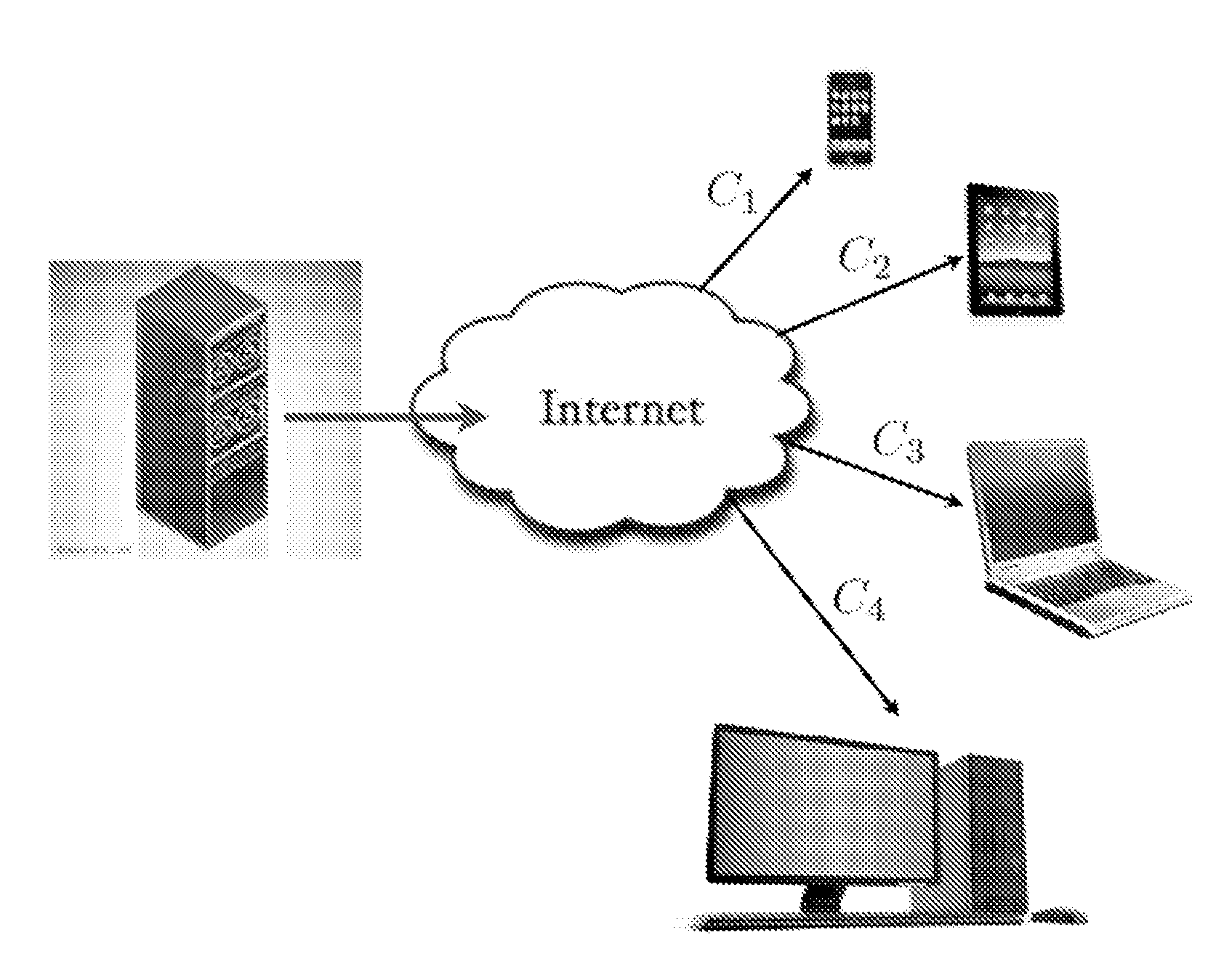
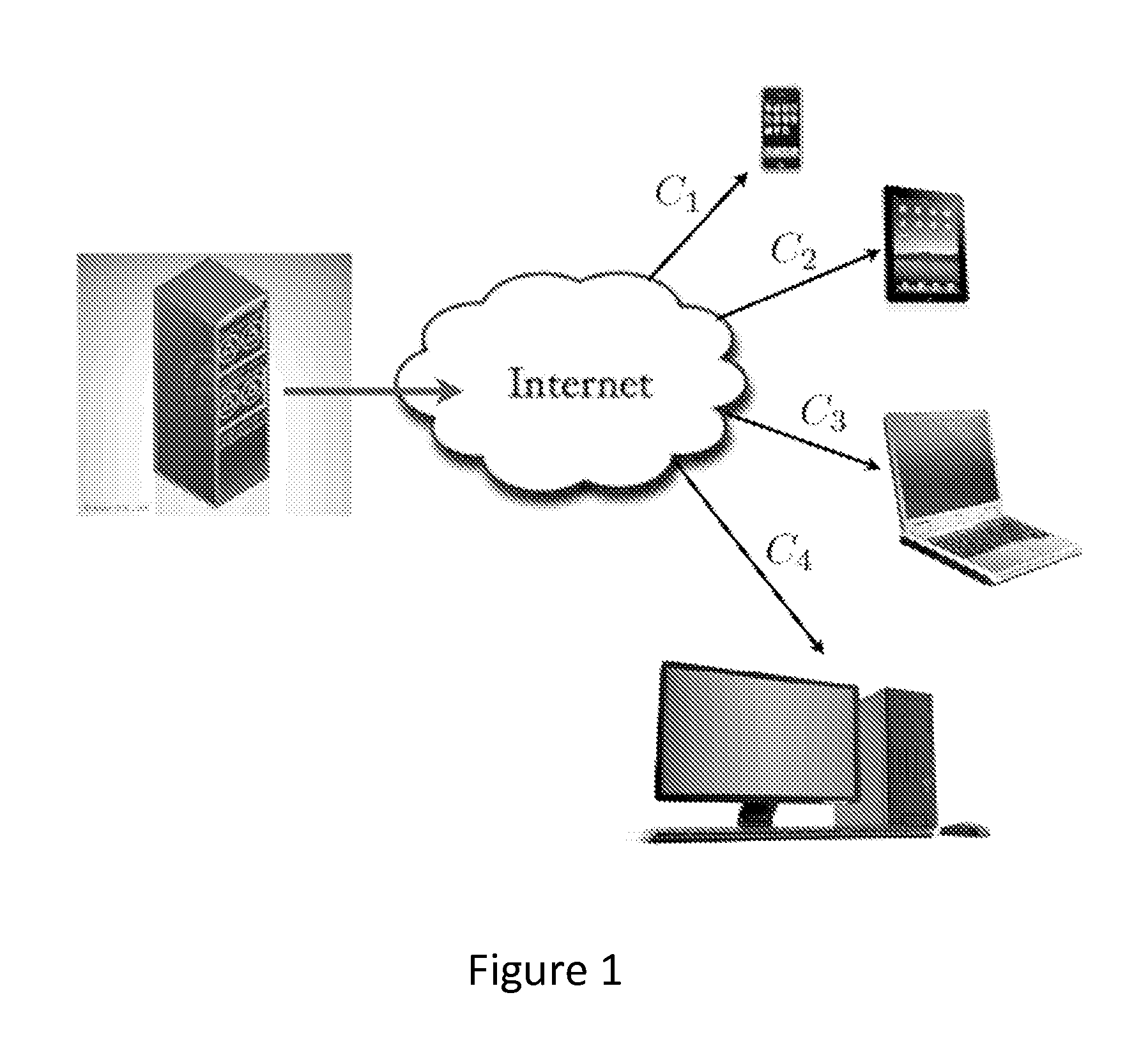
[0070]As an example of the application of the system optimization framework developed above, we consider the case of lossy multicasting of digital (gray-scale) images over the BEBC. Two embodiments are designed according to the MMDP criterion. The former is based on the concatenation of a state-of-the art image coder, JPEG2000, with standard non-systematic Raptor codes. The latter is based on scalar quantization with linear index coding, as presented above.

[0071]JPEG2000 and Raptor codes—this case can be cast within the problem formulation set forth above, for a single source component (s=1) and where JPEG2000 plays the role of the successive refinement source code. JPEG2000 produces a bit-stream of source-encoded bits with the property that the encoder output for any given bit rate is a prefix of the output for any higher bit rate. For a given source image we can generate a set of R-D points by considering an increasing number of JPEG2000 output bits, sequentially. We considered th...


PUM


Abstract

A source channel encoder, source channel decoder and methods for implementing such devices are disclosed herein. The source channel encoder includes a linear transform encoder configured to generate a plurality of source components. A successive refinement quantizer is configured to generate a plurality of bit planes based on the source components. A systematic linear encoder configured to map the bit planes into channel-encoded symbols. The linear transform encoder may be configured to apply a Discrete Cosine Transform (DCT) or a Discrete Wavelet Transform (DWT). The linear transform encoder may be configured for differential encoding.

Description

CROSS-REFERENCE TO PRIOR FILED APPLICATIONS[0001]This application claims priority to earlier filed provisional application 61 / 416,986 filed on Jun. 18, 2010, which is incorporated herein in its entirety.UNITED STATES GOVERNMENT RIGHTS[0002]This invention was made with government support under CNS-06-25637 and NeTs-07-22073 awarded by U.S. National Science Foundation. The government has certain rights to this invention.FIELD OF INVENTION[0003]The invention relates to communications systems generally and more particularly relates to multicasting multimedia streaming systems.BACKGROUND[0004]Multimedia streaming over heterogeneous digital networks is one of the fastest growing applications both in terms of traffic demands and in terms of market potential. Systems can include a server, multicasting a multi-media source (audio / video) to a number of clients. Such systems lack a mechanism to provide real-time multicasting where the decoding delay is the same for all users; but each user rec...

Claims


Application Information

Patent Timeline
Patent Type & Authority Applications(United States)
IPC IPC(8): H04N7/26H04N7/30
CPCH04N19/34
Inventor YILMAZ, OZGUN BURSALIOGLUCAIRE, GIUSEPPEFRESIA, MARIAPOOR, HAROLD VINCENT
Owner UNIV OF SOUTHERN CALIFORNIA
Why Eureka
Try Eureka