Disk-based fluid sample collection device

a technology of fluid sample collection and disk, which is applied in the direction of positive displacement liquid engines, laboratory glassware, instruments, etc., to achieve the effect of improving fluid collection

Active Publication Date: 2012-02-16
NAT TAIWAN UNIV
View PDF6 Cites 11 Cited by
  • Summary
  • Abstract
  • Description
  • Claims
  • Application Information

AI Technical Summary

Benefits of technology

[0007]In view of the above description of the conventional techniques, it is a major issue for this field to provide a fluid sample separation technique that realizes high throughput of cell selection, easy operation, low cost, simple facility, and excellent sensitivity and reliability. Further, it is also a key issue for this field to properly collect waste fluid or desired target fluid obtained in the fluid sample separation operation.
[0008]Thus, an objective of the present invention is to provide a fluid separation and collection device, which is of low cost, is easy for collection of sample fluid, and is easy for detection and observation, for being used to collect separated target components of a fluid sample in a fluid separation operation.
[0010]In a preferred embodiment of the present invention, at least one magnetic unit is set on a top of the sealing cover at a location corresponding to the sample processing reservoir of the microfluidic disk for providing a uniform magnetic force of predetermined magnitude on the sample processing reservoir to improve fluid collection.

Problems solved by technology

In view of the above description of the conventional techniques, it is a major issue for this field to provide a fluid sample separation technique that realizes high throughput of cell selection, easy operation, low cost, simple facility, and excellent sensitivity and reliability.
Further, it is also a key issue for this field to properly collect waste fluid or desired target fluid obtained in the fluid sample separation operation.

Method used


Image

  • Disk-based fluid sample collection device
  • Disk-based fluid sample collection device
  • Disk-based fluid sample collection device

Examples


Embodiment Construction

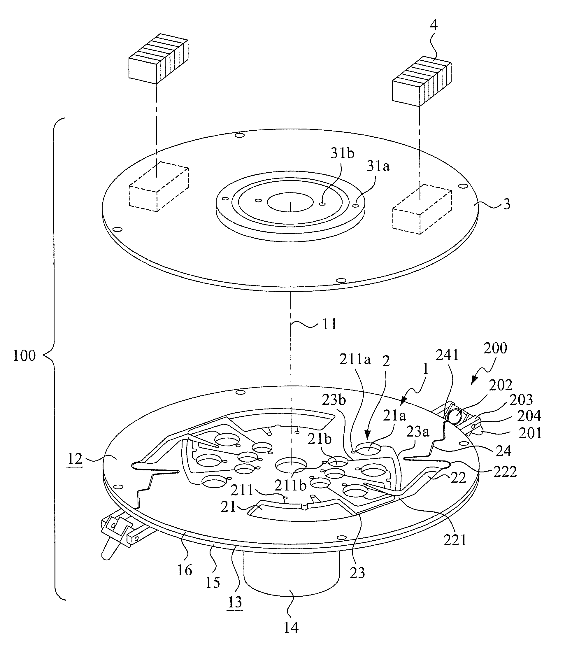
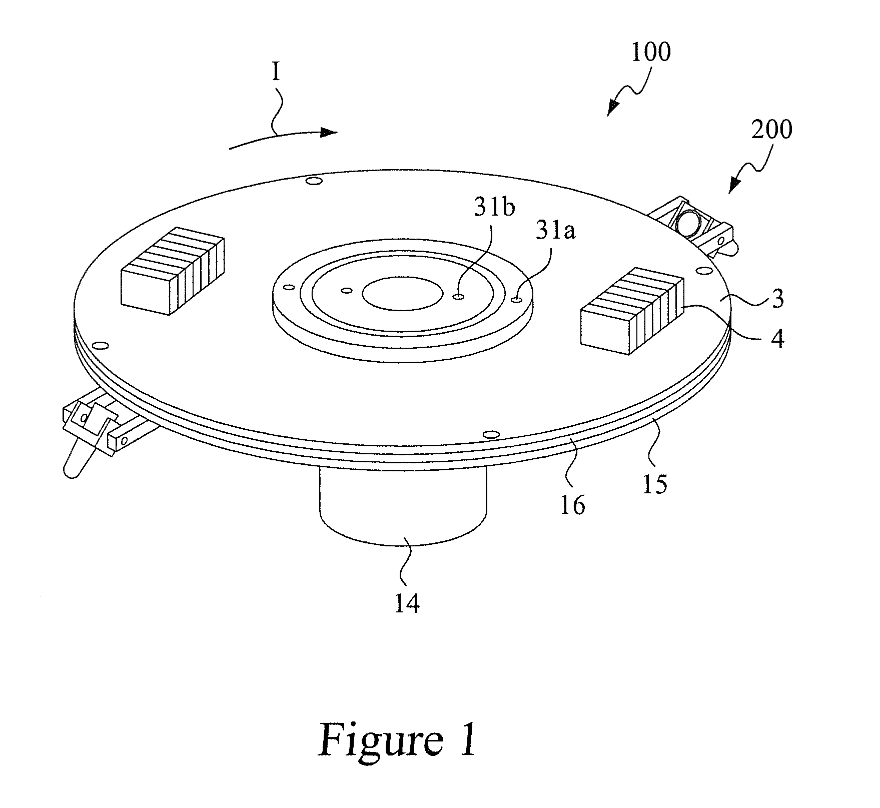
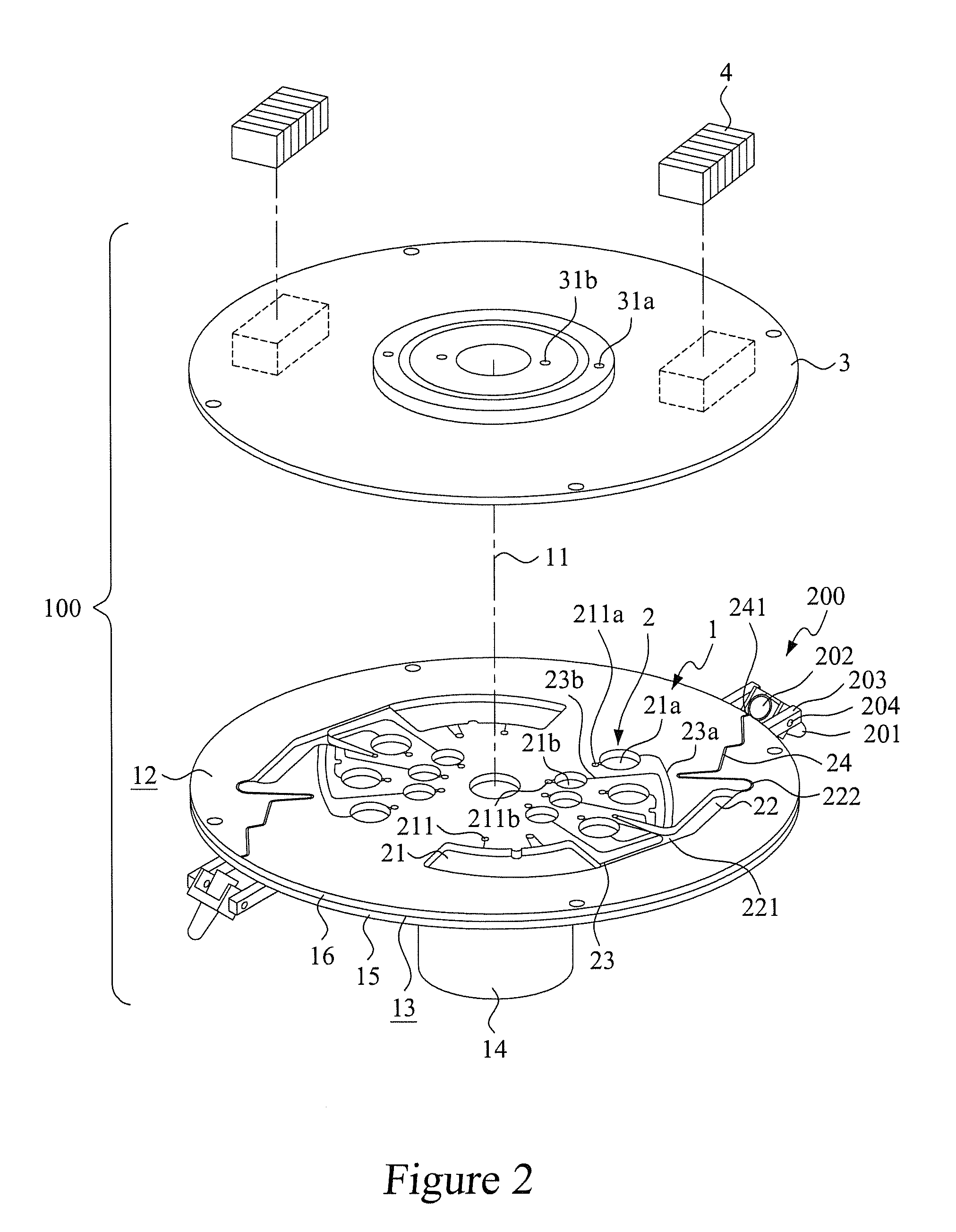
[0026]With reference to the drawings and in particular to FIG. 1, which is a perspective view showing a preferred embodiment of the present invention, and FIG. 2, which is an exploded view showing a microfluidic disk according to the preferred embodiment of the present invention, the present invention provides a disk-based fluid sample separation system, generally designated at 100, which comprises a microfluidic disk 1 having a geometric center 11, a top surface 12, and a circumferential surface 13, which serves as an outflow boundary of the disk. The geometric center 11 is coupled to a spindle of a rotation driving device 14, whereby the microfluidic disk 1 is selectively driven by the rotation driving device 14 to rotate about the geometric center 11, which serves as a rotation center, in a predetermined rotation direction I.

[0027]The microfluidic disk 1 forms a flow channel pattern 2. In the instant embodiment, the microfluidic disk 1 is composed of a bottom base board 15 and a ...


PUM

PropertyMeasurementUnit
centrifugal forceaaaaaaaaaa
magnetic forceaaaaaaaaaa
angleaaaaaaaaaa

Abstract

A fluid sample collection device for a disk-based fluid separation system is disclosed. The disk-based separation system includes a compact microfluidic disk with at least one flow channel pattern formed on a side surface of the disk. At least one orifice is formed on an outflow boundary of the disk and is designed in fluid communication with the flow channel pattern through a communication channel. The fluid sample collection device includes at least one collection tube having an open end serving as a fluid receiving end and corresponding to the orifice of the disk with a distance. When the disk is rotated, at least a portion of fluid sample in a sample processing reservoir formed on the disk is delivered by centripetal force through the communication channel and the orifice, and finally the expelling fluid sample is collected in the collection tube.

Description

FIELD OF THE INVENTION[0001]The present invention relates to a fluid separation device, and in particular to a fluid collection device that is mounted to an outflow boundary of a microfluidic disk of a fluid separation device to collect a fluid sample that is discharged through an orifice formed in the outflow boundary of the microfluidic disk when the microfluidic disk is set in rotation.BACKGROUND OF THE INVENTION[0002]Techniques for fluid sample separation are of wide applications, such as separation of cells, separation of fetal cells, cell separation for whole blood samples, and separation of endothelial colony forming cells (ECFC) contained in umbilical cord blood (UCB).[0003]For example, detection and quantification of cancer cells or rare cells present in body fluids are regarded as a potential indicator for clinical diagnoses, prognostication, and biomedicine research. For example, circulating tumor cells (CTC) are rare in the blood of patients with metastatic cancer, and i...

Claims


Application Information

Patent Timeline
Patent Type & Authority Applications(United States)
IPC IPC(8): G01N1/10
CPCB01L3/502715B01L3/502723B01L3/502738B01L2200/027B01L2300/045B01L2300/048B01L2300/0803B01L2400/0409B01L2400/0644G01N35/00069G01N2035/0449B01L3/50273Y10T436/2575Y10T436/25Y10T436/11
Inventor WO, ANDREW MAN CHUNGCHEN, CHEN-LINYANG, CHENG WEIPAN, YU-CHENG
Owner NAT TAIWAN UNIV
Why Eureka
Try Eureka