Sample solution introduction kit and sample solution injector

US20120039774A1Inactive Publication Date: 2012-02-16SONY CORP

Image

  • Sample solution introduction kit and sample solution injector
  • Sample solution introduction kit and sample solution injector
  • Sample solution introduction kit and sample solution injector

Examples


embodiment

1. Embodiment

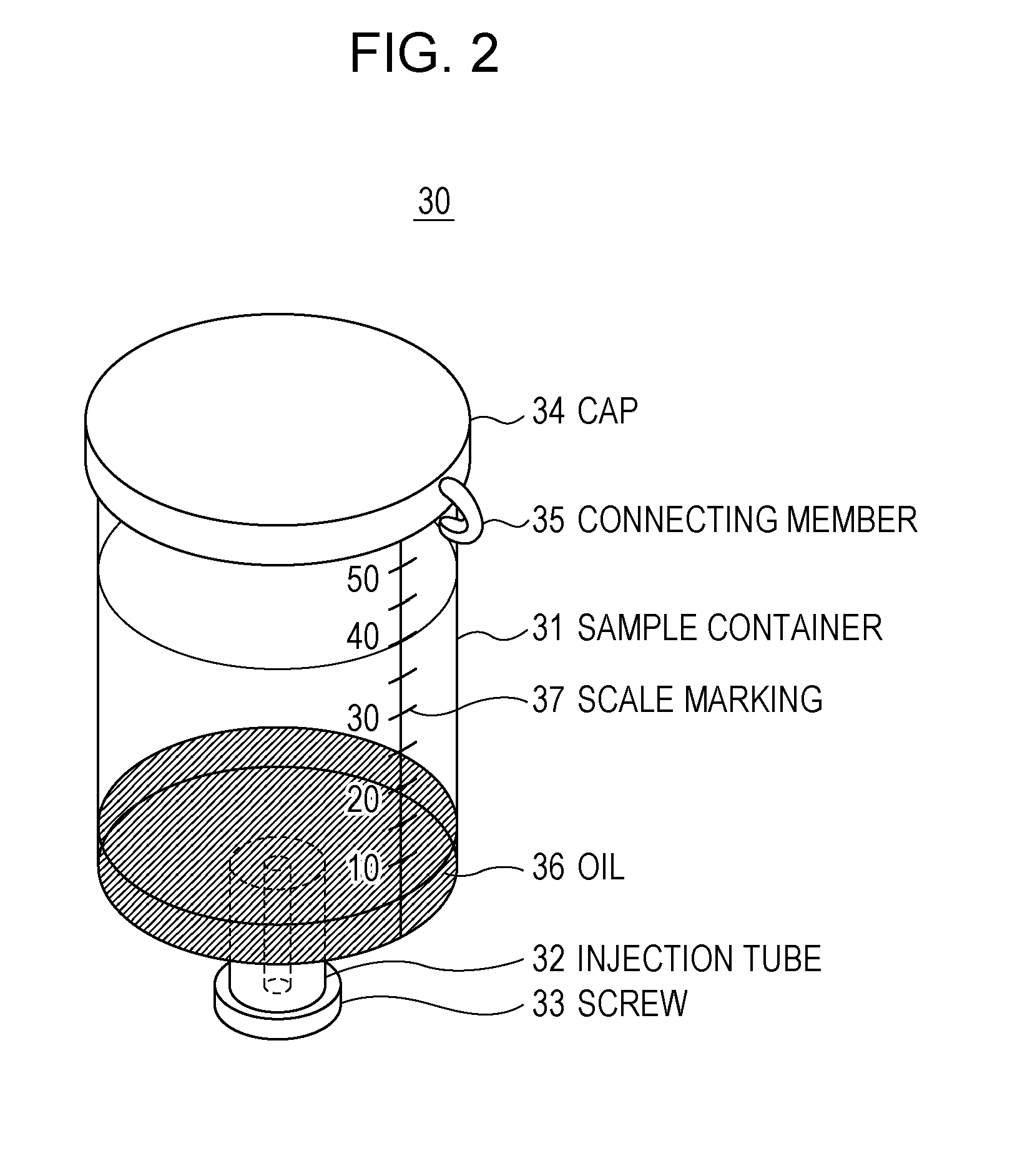
[0033]A sample solution introduction kit according to an embodiment is described. According to the present embodiment, the sample solution introduction kit includes a plate-like member having a plurality of reaction fields (hereinafter referred to as a “reaction substrate”) and a sample injector that injects sample solution into the reaction fields of the reaction substrate. The reaction substrate and the sample injector are packaged together as a set, which is delivered to the site.

[1-1. Structure of Reaction Substrate]

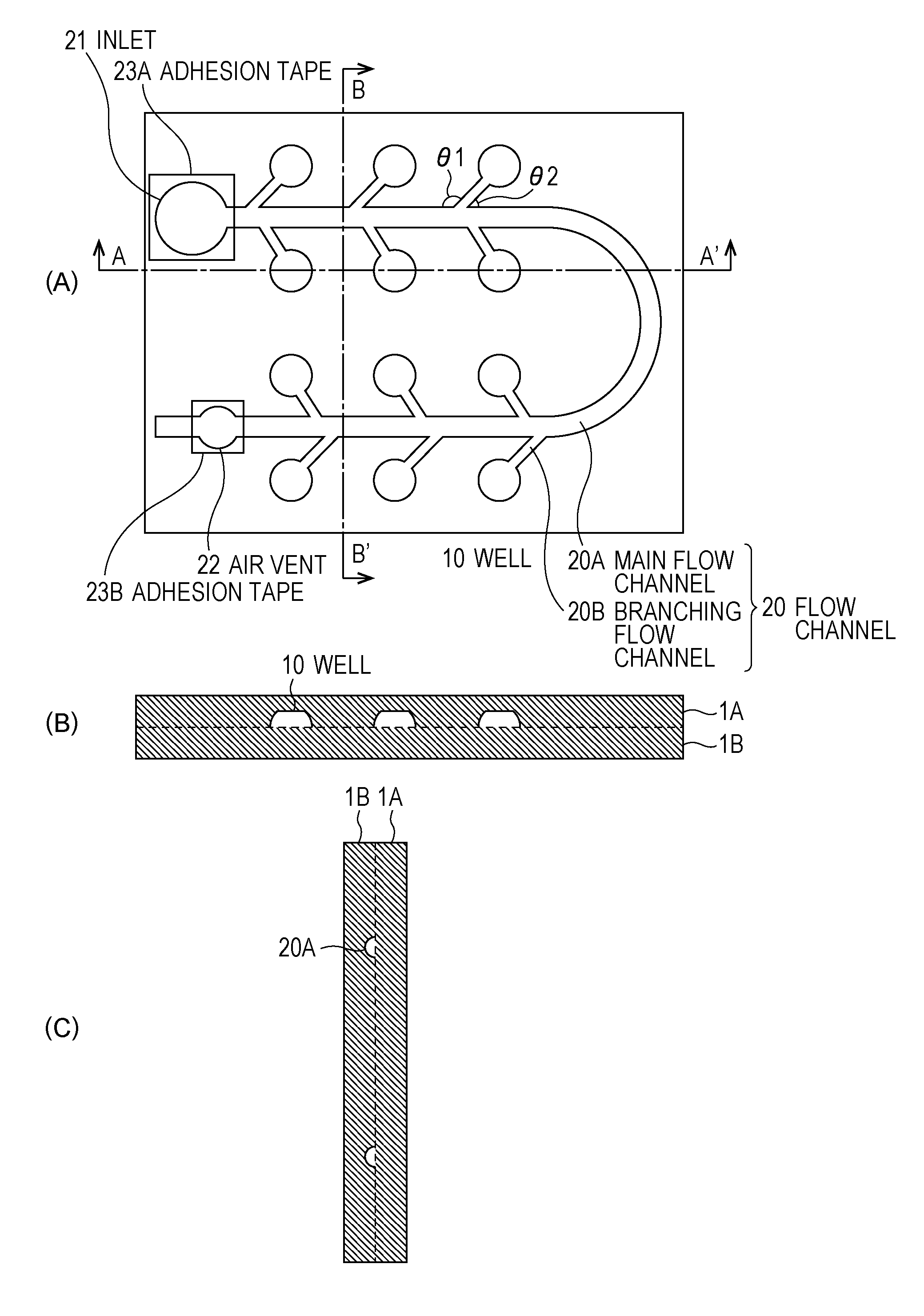
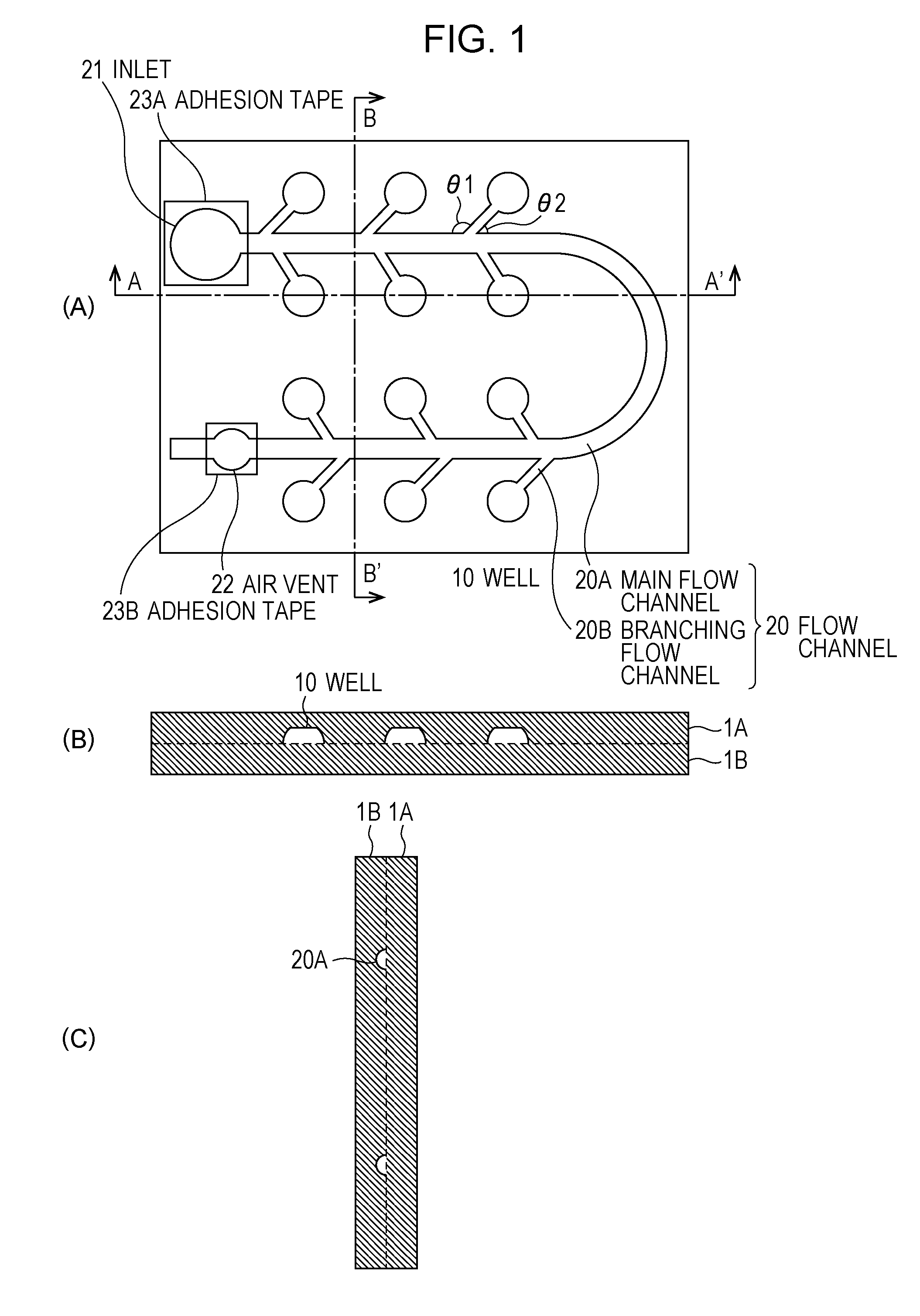
[0034]According to the present embodiment, the reaction substrate is set in a real-time PCR machine (or a PCR machine) at a predetermined position of a reaction chamber. FIG. 1 is a schematic illustration of the structure of the reaction substrate.

[0035]A reaction substrate 1 has a configuration in which a sheet film 1A is bonded to a sheet film 1B by applying heat or ultrasonic waves or using an adhesive agent. PET (polyethylene terephthalate) is used a...


PUM


Abstract

A sample solution introduction kit and a sample solution injector capable of introducing sample solution while reducing the rate of occurrence of an air bubble and having a simplified structure are proposed.A sample solution introduction kit includes a plate-like member and a sample solution injector. The plate-like member has a plurality of spaces formed therein and serving as reaction field and a communication space that communicates with the plurality of spaces therein and that has a portion defining an opening formed in a surface of the plate-like member, and the sample solution injector includes a container containing the sample solution, a tube that communicates with the bottom of the container and that is insertable into the opening, a stopper removably fitted into an opening formed at a top end of the tube, and liquid held in the container, and the liquid is insoluble in the sample solution and is lighter than the sample solution.

Description

TECHNICAL FIELD [0001]The present invention relates to a sample solution introduction kit and a sample solution injector that are suitable in a technical field for amplifying nucleic acid.BACKGROUND ART [0002]In real-time PCR machines or PCR machines, a substrate including a plurality of microcontainers that serve as amplification reaction fields for nucleic acid is used. In an existing technique, a substrate including a carrier, a cover that covers the surface of the carrier and that is bonded to the carrier, and void part provided between the carrier and the cover and corresponding to microcontainers and a flow channel connecting the microcontainers to one another is proposed (refer to NPL 1).[0003]In addition, a device that prevents air bubbles from being generated in void part or from entering the void part when sample solution is introduced into the void part is proposed (refer to PTL 1). The device includes a liquid addition unit into which liquid is added and a liquid introdu...

Claims


Application Information

Patent Timeline
16 Feb 2012
Publication
US20120039774A1
IPC
B01J14/00
CPC
B01L3/502715; B01L3/502723; B01L2200/027; B01L2200/0605; B01L2400/0487; B01L2200/142; B01L2300/0816; B01L2300/0864
Inventors
YOTORIYAMA, TASUKU; SAKAMOTO, NAOHISA